


Schnorr Disc Springs
PERMISSIBLE STRESS FOR DYNAMIC LOADS
Disc Spring Engineering
Maximum load - minimum space - maximum flexibility
PERMISSIBLE STRESS FOR DYNAMIC LOADS
Dynamic loads occur in disc springs when the load continuously changes between a preload deflection s1 and a deflection s2. Under the influence of a change in stress of σh, dynamically loaded disc springs can be divided into two groups by service life (see also DIN 50100):
Disc springs for longer life. These disc springs are intended to withstand load cycles of a least 2 . 106 and more without breaking. If a considerably longer life is required, please contact us. It may be that only an endurance test can provide exact information.
Disc springs with a limited service life. These disc springs are intended to achieve a limited number of load cycles in the range between 104 < N < 2 . 106 before failure.
Critical Stress Affecting Dynamic Failure
For disc springs carrying dynamic loading, the calculated tensile stress on the underside of the spring are the determining factors, as fatigue cracks always start here. In dependency on the dimensional ratio δ = De/Di and ho/t and the relative deflection s/ho, the largest stress range σh may occur at both point ll and lll is decisive can be derived figure 17 for springs with and without contact flats.
Figure 17 – click to enlarge
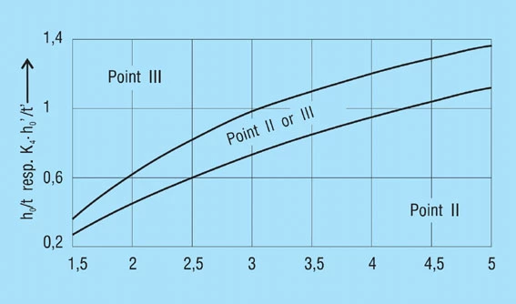
We recommend calculating the stress for both points using formulas 11 and 12. Use the larger value to determine fatigue life using the applicable diagrams (figure 18 – 20).
Minimum Preload to Prevent Superficial Cracks
After head treatment all discs springs are going to be scragged or pre-stressed, which causes a plastic deformation in the region of cross-sectional point l. This results in residual tensile stress at this point in the unloaded spring. When loaded there is then a change from tensile to compressive stress which can result in the formation of cracks during dynamic loading. To avoid these the tensile stress must be balanced out by applying a suitable pre-stress. Therefore, dynamically loaded disc springs should be preloaded to at least s = 0.15 to 0.20 ho.
Permissible Stress
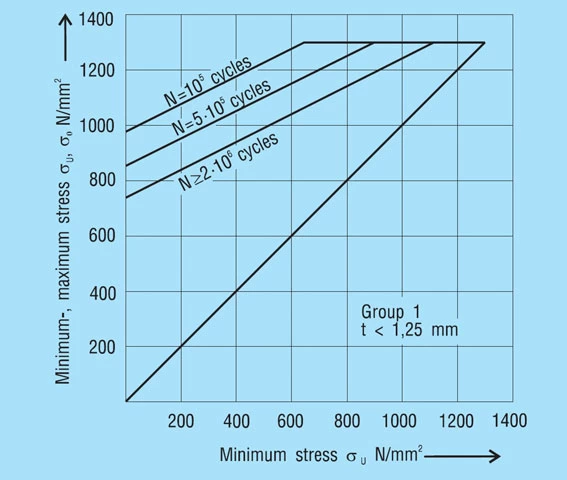
The stress calculated for the working range of the spring is compared with the fatigue diagrams in figure 18 – 20. These provide standard values of the permissible stress range σH for N > 2.106, N = 5.105 and N = 105 load cycles in dependency on the minimum stress σU for dynamically loaded, non-shot-peened disc springs. Intermediate values for other load cycles can be estimated.
A fatigue diagram is indicated for each of the 3 manufacturing groups as per DIN 2093. These groups are divided by the disc thickness as follows:
Group 1: t less than 1.25mm
Group 2: t = 1.25 to 6mm
Group 3: t over 6 to 14mm
These diagrams were developed from laboratory tests on test machines with an even sinusoidal load by means of statistical evaluation, whereby a survival rate of 99% was assumed. This means that for a large enough sample a failure rate of 1% can be expected due to fatigue.
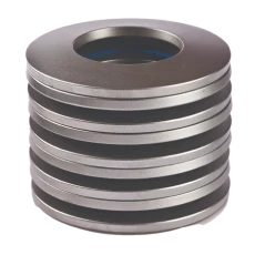
The diagrams are applicable to single springs and spring stacks with up to 10 single springs stacked in series, operating at room temperature with hardened and perfectly finished inner or outer guides and minimum preload deflection of s1 = 0.15 to 0.20 ho.
Figure 18 – click to enlarge
It should be noted that in practice the type of loads applies in many cases deviates from a nearly sinusoidal frequency. In the case of an impact-type load cycle and as the result of natural frequencies, the actual material loading in considerably greater than the calculated value. The values of the diagrams may only be used for these types of loading under inclusion of the appropriate safety factors.
For disc springs of materials other than those specified in DIN 2093, for spring stacks with more than 10 or with multiply parallel-stacked individual springs, and in the case of unfavourable influences of a chemical or thermal nature, sufficient data to predict fatigue are not yet available. In such cases additionally safety factors must also be applied we recommend you contact us.
Figure 19 – click to enlarge
Figure 20 – click to enlarge


