Disc Springs Friction Causes & Calculations
Disc Spring Engineering
Maximum load - minimum space - maximum flexibility
Disc Springs FRICTION
Due to friction, the actual loads obtained when loading and unloading the spring stack may deviate from the figures calculated. These variations are in many cases inconvenient, but at times required for application reasons. Therefore, it is often necessary to calculate the friction and take this into consideration.
Causes of Friction
The total friction with disc spring stacks arises because of 4 different components (figure 34 below):

Friction on the end abutments through the radial movement between the spring and the abutment surface. This only occurs with the end springs in the stack, as there is no relative movement between the other springs to each other.
Friction of the springs on the guide due to axial movement of the springs during deflection.
Friction between springs in the case of parallel stacking.
The first 3 types of friction occur with single springs and single series spring stacks. It is therefore a fact that friction with disc springs is always greater than with coil springs.
The Magnitude and Factors Influencing Friction
The amount of friction depends on very many factors:
Geometric factors:
- Shape of the cross section
- Radii on the corners
- Amount of guide clearance
- Surface roughness of the springs and guide elements
Material factors:
- Material of the springs and guide elements
- Hardness of the springs and guide elements
- Surface protection of the springs
- Type of lubricant
Assembly factors:
- Number of parallel stacked springs
- Length of the spring stack
Load dependant factors:
- Length of spring stroke
- Speed of loading (frequency)
The value of the different factors on the total friction varies considerably from case to case and we can only give the following indications:
A frequently underrated influence is the surface treatment. For example, zinc plated springs have less friction than those phosphated. With parallel stacking the greatest friction is between the springs, with an increase in proportion to the number of parallel springs. This can, however, be reduced by means of a suitable grease.
It is known from experience that relatively large deflection s/ho or (s2 – s1)/ho cause more friction than smaller deflections. These factors should all be considered for high frequency spring applications. Because of the large number of influences, it is not possible to derive an exact calculation for friction in disc spring stacks.
However, from many tests with various spring sizes a figure has been derived of +2.5% per parallel spring (+ loading, – unloading). This results in the following values:
Influence of friction on spring load | |
1 single spring | +2… 3% |
2 in parallel | +4… 6% |
3 in parallel | +6… 9% |
4 in parallel | +8… 12% |
5 in parallel | +10… 15% |
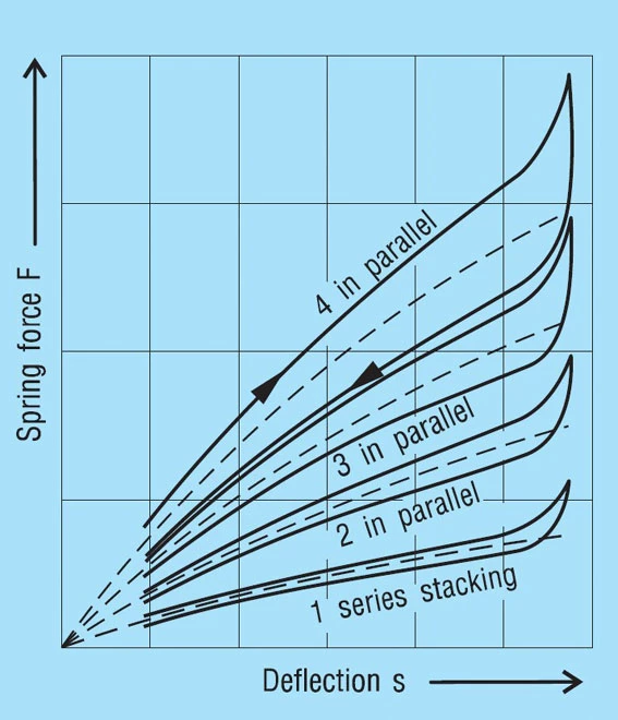
Figure 35 below shows the principal load variations for one to 4 springs in parallel.
Calculation of Friction as per DIN 2092
DIN 2092, Issue 1/92 gives a method of calculating the friction FR on spring load. This omits the internal friction and the friction on the guide rod. This must be obtained through an additional calculation. The values below for surface and edge friction to DIN 2092 give a relatively wide range.
Therefore, it is our opinion that, although this process is theoretically correct, in the end it does not provide any better results than the consideration of the friction with a simple, percentile addition. For completeness, we have shown this calculation method below.
The following formula applies:
Formula 26

Where:
F = Calculated spring load to formula 7
n = Number of springs in parallel
WM = Coefficient of surface friction
WR = Coefficient of edge friction
– = On loading
+ = On unloading
With n = 1 formula 26 describes relationships for a single spring between 2 flat plates. For the friction coefficients WM and WR, DIN 2092 gives the following values:
Series Per DIN 2093 | WM | WR |
| Series A | 0.005…0.030 | 0.03…0.05 |
| Series B | 0.003…0.020 | 0.02…0.04 |
| Series C | 0.002…0.015 | 0.01…0.03 |
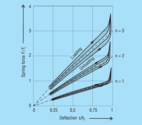
When calculated with these values, formula 26 provides the following numbers, which are considerably easier to understand:
Alteration of the calculated spring load through the friction is in %.
+ = Increase in load when loading / – = Reduction in load when unloading
| n = 1 | n = 2 | n = 3 | |
| Series A | +3.09…+5.26 | +3.63…+8.70 | +4.17…+12.36 |
| -2.91…-4.76 | -3.38…-7.41 | -3.85…-9.91 | |
| Series B | -2.04…+4.17 | +2.35…+6.38 | +2.67…+8.70 |
| -1.96…-3.85 | -2.25…-5.66 | -2.53…-7.41 | |
| Series C | +1.01…+3.09 | +1.21…+4.71 | +1.42…+6.38 |
| -0.99…-2.91 | -1.19…-4.31 | -1.38…-5.66 |
These results are presented in figure 36 below.
Lubrication
The large variation in figure 36 shows the influence of lubrication on the friction. The choice of the correct lubricant is therefore often of decisive influence. As well as reducing friction. It can prevent galling of one spring on another when stacked in parallel. Similarly, it can help prevent corrosion. The lubricants which may be used are:
- Oil is frequently used for springs in machine construction, especially with central lubrication or an assured continuous oil supply.
- Grease is more suitable if re-lubrication is difficult or cannot be done on a regular basis.
- Slip paints are based on MoS2 and are an elegant solution to providing permanent lubrication. It also provides a high degree of corrosion resistance.
The Effects of Friction
Friction mainly effects the deflection of the spring, i.e. it modifies the spring loads. It must be added when loading the spring and subtracted when the spring is unloaded. Between the actual loading and unloading curve there is a hysteresis loop. The effect of the number of parallel springs on the hysteresis is shown in figure 35. This frictional work is turned into heat and with high frequency dynamic loading this can be considerable. In such cases, single stacked discs springs should be preferred and good lubrication is essential.
With spring energy storage the hysteresis is a total loss and cannot be recovered. However, with springs for damping, this hysteresis effect is useful and the frictional work is a measure of the damping.


