


These are valid for all disc springs.
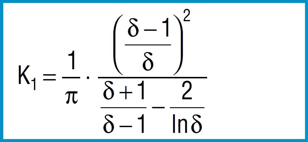
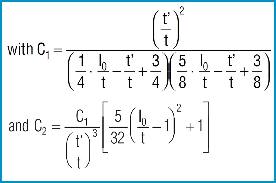
Characteristics
Formula 2

Formula 3
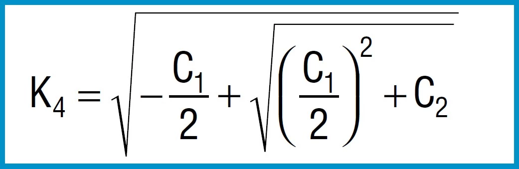
Formula 4

Formula 5

Formula 6
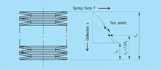
Spring Force
Formula 7
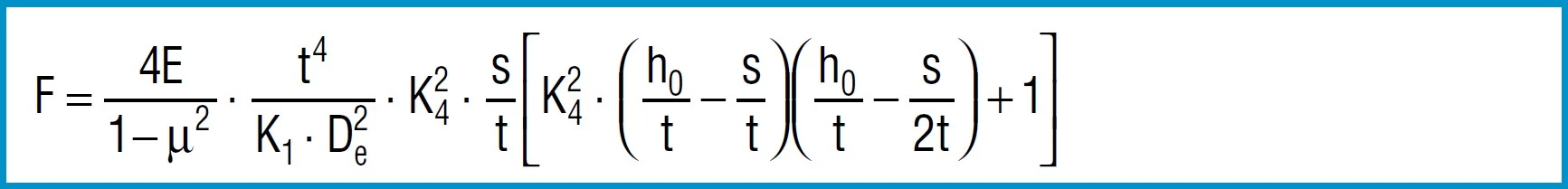
For disc springs manufactured to group 1 and 2 K4 = 1:
Formula 8a

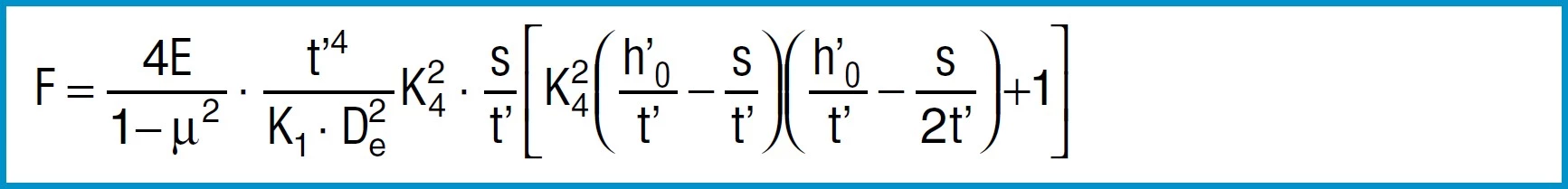
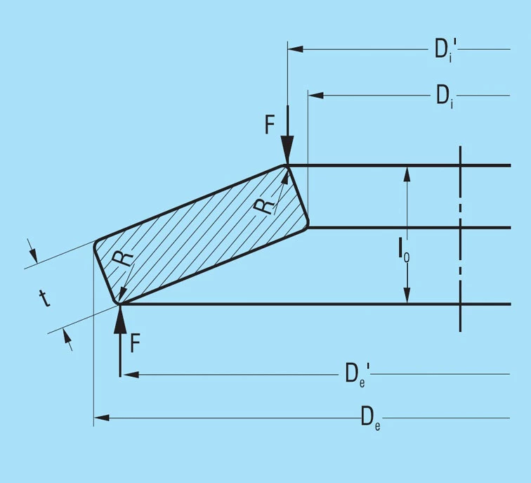
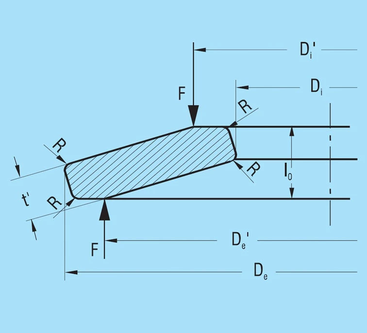
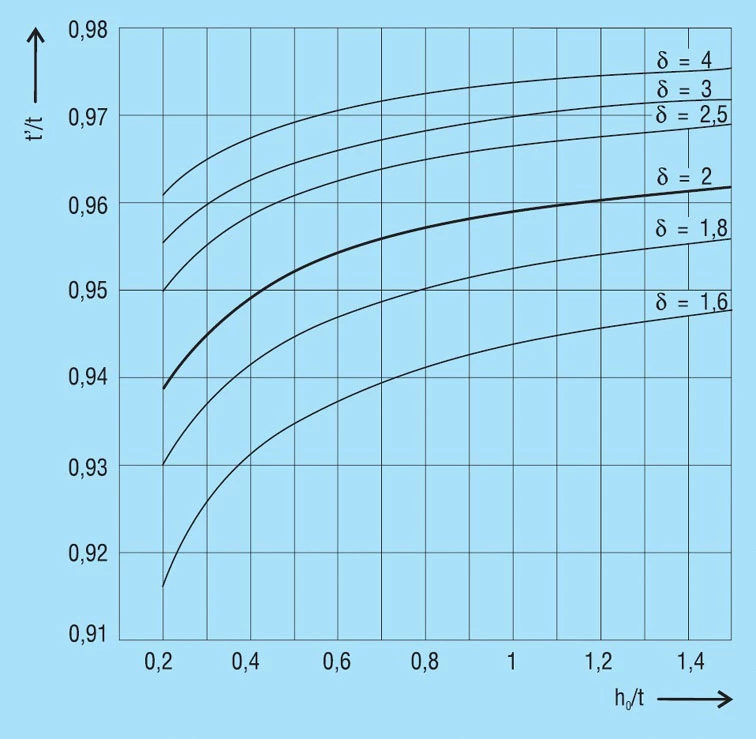
For disc springs manufactured to group 3 with contact flats and reduced thickness, t’ and ho’ must be used
(ho’=lo-t’):
Formula 8b
Young’s modulus ‘E’ is virtually independent of the heat treatment condition and tensile strength of the material.
For steel springs with dimensions in accordance with DIN 2093, formula 7 provides values which correspond closely to the measured values.
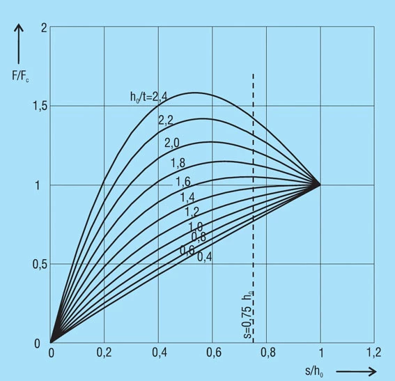
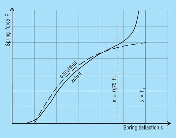
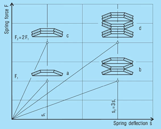
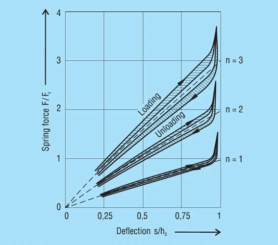
The force of a disc spring does not increase linearly with the deflection, but is always regressively curved. Its pitch, i.e. the rate, decreases with increasing stroke. The ratio of curvature is determined exclusively by the ratio ho/t, as can be seen in figure 3.
Figure 3 – click to enlarge
Stress Calculations
Formula 9
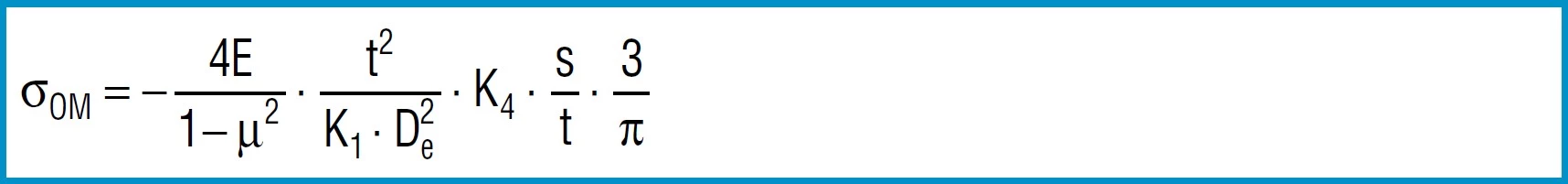
Formula 10

Formula 11

Formula 12

Formula 13

Here
4E= 905 495 N / mm2
1 – µ2
also applies to spring steel. Positive values are tensile stress and negative values are compressive stress. It is important to remember that this the calculated stress is a normal value and that the actual stress is considerably lower, as it is considerably influences by the ever-present internal stress.
Spring Rate
Through differentiation of the spring load F in accordance with the reflection s, the following formula is obtained for spring rate R:
Formula 14

The spring rate between any two adjacent points F1,s1an F2, s2can be approximated by means of the following simple formula:
Formula 15

Spring Work
The work done by a disc spring can be obtained by integrating formula 7 for the load F according to the deflections:
Formula 16

For a limited area of application it can be integrated between the two deflections s1and s2.


| De or Di [mm] | Permissible deviation in mm | ||
| De | Di | Concentricity | |
| Over 3-6 | 0/-0.12 | +0.12/0 | 0.15 |
| Over 6-10 | 0/-0.15 | +0.15/0 | 0.18 |
| Over 10-18 | 0/-0.18 | +0.18/0 | 0.22 |
| Over 18-30 | 0/-0.21 | +0.21/0 | 0.26 |
| Over 30-50 | 0/-0.25 | +0.25/0 | 0.32 |
| Over 50-80 | 0/-0.30 | +0.30/0 | 0.60 |
| Over 80-120 | 0/-0.35 | +0.35/0 | 0.70 |
| Over 120-180 | 0/-0.40 | +0.40/0 | 0.80 |
| Over 180-250 | 0/-0.46 | +0.46/0 | 0.92 |
| Over 250-315 | 0/-0.52 | +0.52/0 | 1.04 |
| Over 315-400 | 0/-0.57 | +0.57/0 | 1.14 |
| Over 400-500 | 0/-0.63 | +0.63/0 | 1.26 |
| t or t’ [mm] | Tolerance at t [mm] | |
| Group 1 | 0.2-0.6 | +0.02/-0/06 |
| >0.6 -<1.25 | +0.03/-0.09 | |
| Group 2 | 1.25-3.8 | +0.04/-0.12 |
| >3.8-6.0 | +0.05/-0.15 | |
| Group 3 | >6.0-16.0 | +0.30/-0.30 |
| t [mm] | Tolerance at lo [mm] | |
| Group 1 | <1.25 | +0.10/-0.05 |
| Group 2 | 1.25-2.0 | +0.15/-0.08 |
| >2.0-3.0 | +0.20/-0.10 | |
| >3.0-6.0 | +0.30/-0.15 | |
| Group 3 | >6.0-16.0 | +0.30/-0.30 |
| t [mm] | Tolerance for F at the test length lp=lo-0.75 ho | |
| Group 1 | <1.25 | +25%/-7.5% |
| Group 2 | 1.25-3.0 | +15%/-7.5% |
| >3.0-6.0 | +10%/-5% | |
| Group 3 | >6.0-6.0 | +5%/-5% |


Diameter Tolerances
For the outside diameter De, the tolerance field h12 is applied, and for the inner diameter Di, it is H12. For the concentricity the tolerances applied are: for De to 50mm: 2 . IT 11 for Di over 50mm: 2 . IT 12| De or Di [mm] | Permissible deviation in mm | ||
| De | Di | Concentricity | |
| Over 3-6 | 0/-0.12 | +0.12/0 | 0.15 |
| Over 6-10 | 0/-0.15 | +0.15/0 | 0.18 |
| Over 10-18 | 0/-0.18 | +0.18/0 | 0.22 |
| Over 18-30 | 0/-0.21 | +0.21/0 | 0.26 |
| Over 30-50 | 0/-0.25 | +0.25/0 | 0.32 |
| Over 50-80 | 0/-0.30 | +0.30/0 | 0.60 |
| Over 80-120 | 0/-0.35 | +0.35/0 | 0.70 |
| Over 120-180 | 0/-0.40 | +0.40/0 | 0.80 |
| Over 180-250 | 0/-0.46 | +0.46/0 | 0.92 |
| Over 250-315 | 0/-0.52 | +0.52/0 | 1.04 |
| Over 315-400 | 0/-0.57 | +0.57/0 | 1.14 |
| Over 400-500 | 0/-0.63 | +0.63/0 | 1.26 |
Thickness Tolerances
Tolerances allowed in DIN 2093 are as follows:| t or t’ [mm] | Tolerance at t [mm] | |
| Group 1 | 0.2-0.6 | +0.02/-0/06 |
| >0.6-<1.25 | +0.03/-0.09 | |
| Group 2 | 1.25-3.8 | +0.04/-0.12 |
| >3.8-6.0 | +0.05/-0.15 | |
| Group 3 | >6.0-16.0 | +0.30/-0.30 |
Overall Height Tolerances
To ensure the specified spring forces, DIN 2093 allows the overall height tolerance to be slightly exceeded.| t [mm] | Tolerance at lo [mm] | |
| Group 1 | <1.25 | +0.10/-0.05 |
| Group 2 | 1.25-2.0 | +0.15/-0.08 |
| >2.0-3.0 | +0.20/-0.10 | |
| >3.0-6.0 | +0.30/-0.15 | |
| Group 3 | >6.0-16.0 | +0.30/-0.30 |
Load Tolerances
Single Disc Springs
For single disc springs the following maximum deviations are allowed:| t [mm] | Tolerance for F at the test length lp=lo-0.75 ho | |
| Group 1 | <1.25 | +25%/-7.5% |
| Group 2 | 1.25-3.0 | +15%/-7.5% |
| >3.0-6.0 | +10%/-5% | |
| Group 3 | >6.0-6.0 | +5%/-5% |

Causes of Friction
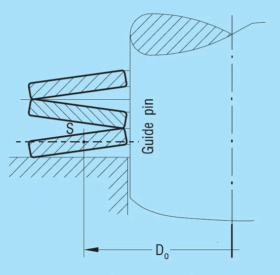
The total friction with disc spring stacks arises because of 4 different components (figure 34 below):
The Magnitude and Factors Influencing Friction
The amount of friction depends on very many factors: Geometric factors:- Shape of the cross section
- Radii on the corners
- Amount of guide clearance
- Surface roughness of the springs and guide elements
- Material of the springs and guide elements
- Hardness of the springs and guide elements
- Surface protection of the springs
- Type of lubricant
- Number of parallel stacked springs
- Length of the spring stack
- Length of spring stroke
- Speed of loading (frequency)
| Influence of friction on spring load | |
| 1 single spring | +2… 3% |
| 2 in parallel | +4… 6% |
| 3 in parallel | +6… 9% |
| 4 in parallel | +8… 12% |
| 5 in parallel | +10… 15% |
Calculation of Friction as per DIN 2092
DIN 2092, Issue 1/92 gives a method of calculating the friction FR on spring load. This omits the internal friction and the friction on the guide rod. This must be obtained through an additional calculation. The values below for surface and edge friction to DIN 2092 give a relatively wide range.
Therefore, it is our opinion that, although this process is theoretically correct, in the end it does not provide any better results than the consideration of the friction with a simple, percentile addition. For completeness, we have shown this calculation method below.
The following formula applies:
Formula 26
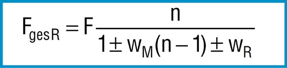
Where:
F = Calculated spring load to formula 7
n = Number of springs in parallel
WM = Coefficient of surface friction
WR = Coefficient of edge friction
– = On loading
+ = On unloading
With n = 1 formula 26 describes relationships for a single spring between 2 flat plates. For the friction coefficients WM and WR, DIN 2092 gives the following values:
Series Per DIN 2093 | WM | WR |
| Series A | 0.005…0.030 | 0.03…0.05 |
| Series B | 0.003…0.020 | 0.02…0.04 |
| Series C | 0.002…0.015 | 0.01…0.03 |
When calculated with these values, formula 26 provides the following numbers, which are considerably easier to understand:
Alteration of the calculated spring load through the friction is in %.
+ = Increase in load when loading / – = Reduction in load when unloading
| n = 1 | n = 2 | n = 3 | |
| Series A | +3.09…+5.26 | +3.63…+8.70 | +4.17…+12.36 |
| -2.91…-4.76 | -3.38…-7.41 | -3.85…-9.91 | |
| Series B | -2.04…+4.17 | +2.35…+6.38 | +2.67…+8.70 |
| -1.96…-3.85 | -2.25…-5.66 | -2.53…-7.41 | |
| Series C | +1.01…+3.09 | +1.21…+4.71 | +1.42…+6.38 |
| -0.99…-2.91 | -1.19…-4.31 | -1.38…-5.66 |
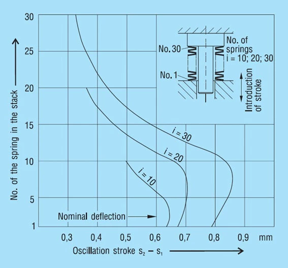
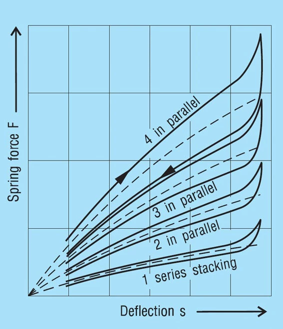
These results are presented in figure 36 below.
Special requirements such as corrosive or high temperature environments often require the use of materials designed for these applications. These materials, in general, have lower tensile strength than standard materials and should only be, if absolutely necessary. These springs have a lower overall height than comparable sizes made of standard materials resulting in lower spring force. This must be taken into consideration using these materials.
Corrosion Resistant Steels
X 10 CrNi 18-8 (1.4310): This chrome nickel alloyed steel as per DIN EN 10151 is the material most used for corrosion resistant springs. Because of its austenitic structure with ferritic inclusions, it cannot be hardened in the usual way, but by cold forming it can obtain the strength required for disc springs. Considerable cold forming in necessary and the strength reduces with increasing thickness. Therefore, the material is normally not available thicker than 2.5mm. In fact, springs can only be supplied to this thickness. Whereas the material in the soft condition is hardly magnetic, the cold working process will make it more or less magnetic again, making it unsuitable for completely non-magnetic springs.
X 7 CrNiAI 17 7 (1.4568): This steel as per DIN EN 10151 precipitation hardened produces an austenitic/ferritic structure. It will also be processed in the work hardened condition and may be hardened by subsequent heat treatment. A disadvantage compared to steel 1.4310 is the lower corrosion resistance and sensitivity to stress corrosion. We therefore only recommend its use for springs over 2.5mm thickness if no other material is available.
X 5 CrNiMo 17 12 1 (1.4401): The strength of this material is somewhat less than either of the two forgoing. Not withstanding that it offers higher corrosion resistance and lowest magnetism. Although also contained in DIN 17224, it is often difficult to obtain and therefore only seldom used.
Steels for Higher Temperatures
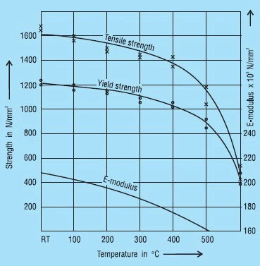
When considering springs for use at higher working temperatures it must be remembered that both tensile strength and Young’s modulus ‘E’ are reduced compared with the values at room temperature.
X 22 CrMoV 12 1 (1.4923): This heat treatable chrome-molybdenum steel has been used very successfully for heat resistant disc springs. Springs of 1.5 to 6mm thickness are made from strip or plate. For thicker springs, forged rings can be used.
Figure 38 shows the mechanical properties and Young’s modulus ‘E’ with respect to temperature. It should be noted that with a chrome content of 12% this steel is not corrosion resistant.
Figure 38 – click to enlarge
X 39 CrMo 17 1 (1.4122): Here we have a chrome-molybdenum alloyed heat treatable martensitic steel which is also suitable for corrosion resistant springs. Because of the molybdenum is may be used up to 400oC. However, at these temperatures both the tensile strength and ‘E’ are reduced.
In order to achieve the required properties, this steel must be hardened to higher values which raises the question of stress corrosion. Unfortunately, in the light of current technical knowledge we cannot completely discount the possibility of delayed brittle fracture.
Copper Alloys
Copper alloys are absolutely non-magnetic and have very good electric conductivity. Moreover, they are corrosion-resistant against many media. These characteristics make them suitable for many disc spring applications.
CuSn 8 (2.1030): Tin bronze as per DIN EN 1654 is an alloy of copper and tin, which obtains is spring properties from cold working. The tensile strength is certainly lower than spring steel and the ‘E’ modulus is only 55% of the value for steel. This must be considered in the spring calculation and allows their use in applications where very low spring loads are required.
CuBe 2 (2.1247): Beryllium copper is an outstanding spring material. This heat treatable alloy has strength values comparable with steel. However, Young’s modulus ‘E’ is only 60% of that for steel. It has very good corrosion resistance and may be used at very low temperatures nearing absolute zero.
Nickel and Cobalt Alloys
From the large number of nickel-chrome and nickel-chrome-cobalt based alloys some have achieved importance for disc springs. By alloying the aluminium, titanium and/or niobium/tantalum they are precipitation hardenable. These materials are very tough, that is to say they have high strength and a low elastic ration. Therefore, the probability of more set in the spring must be considered. Against this are the outstanding fatigue properties. With correct spring proportions this is good over the total spring travel. Because of the material composition they have outstanding corrosion resistant to many media. All these alloys are very expensive and often hard to work, and as a rule have long deliveries. They are therefore only used where no other material is suitable due to technical considerations.
NiCr 20 Co 18 Ti (Nimonic 90) (2.4632, 2.4969): These nickel-chrome-cobalt alloy gives the least problems in processing and is therefore the most often used. It has very good heat resistance and can be used up to 700oC with suitable dimensioning.
NiCr 15 Fe 7 TiAi (Inconel X 750) (2.4669) and NiCr 19 NbMo (Inconel 718) (2.4668): These nickel-chrome alloys are practically cobalt-free, and are therefore used in reactor applications. The hardening process is difficult and expensive. The application is limited and only used in special cases. NIMONIC and INCONEL are trade names of Inco Alloys International.
DURATHERM 600: This is a heat treatable alloy of the cobalt-nickel series with outstanding mechanical properties. At a temperature of 0oC the material in non-magnetic. It can be used at very high temperatures (600oC and over). The very high price of this alloy limits its use to very special applications. DURATHERM is a trade name of Vacuumschmelze GmbH in Hanau.
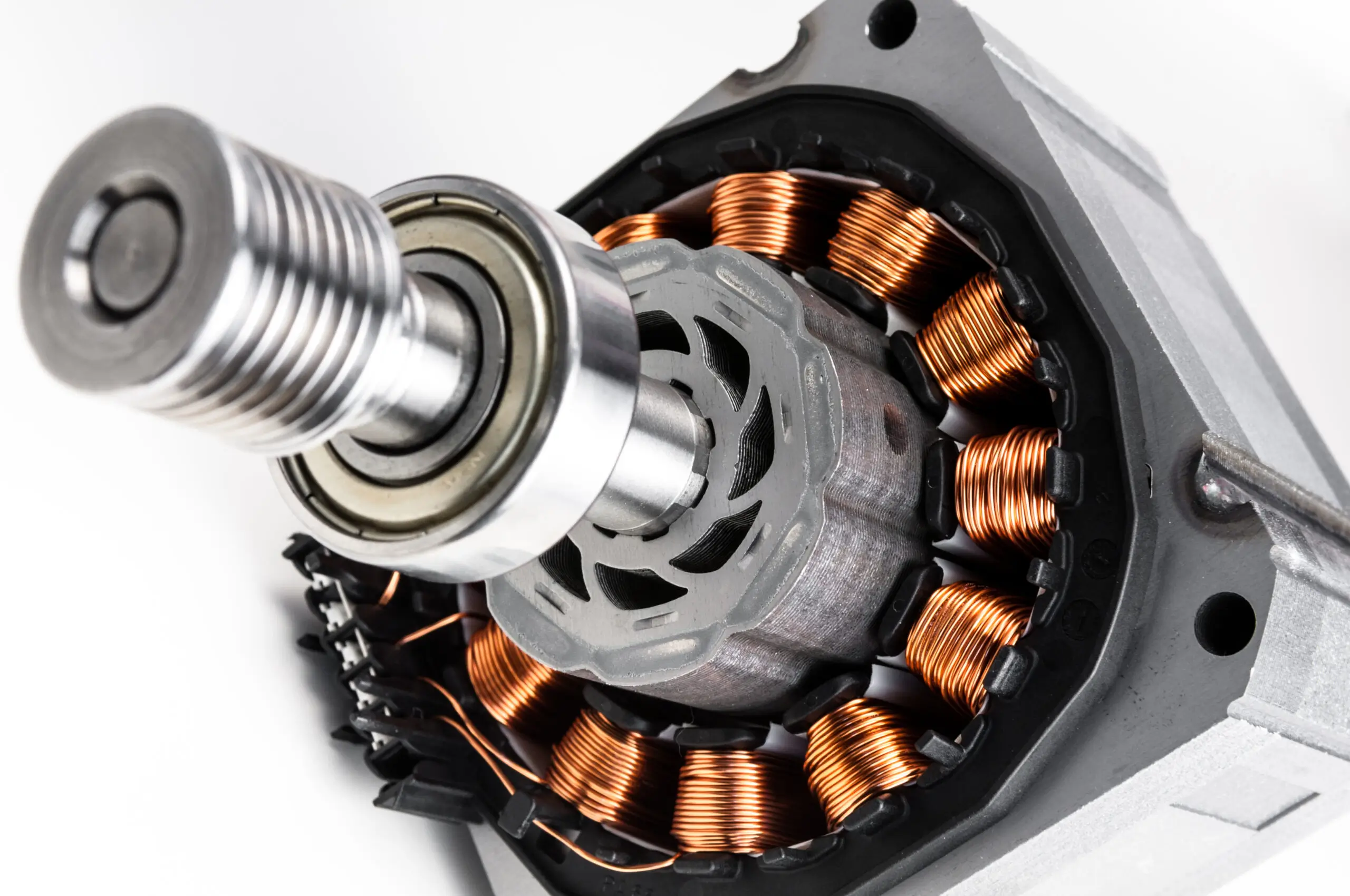
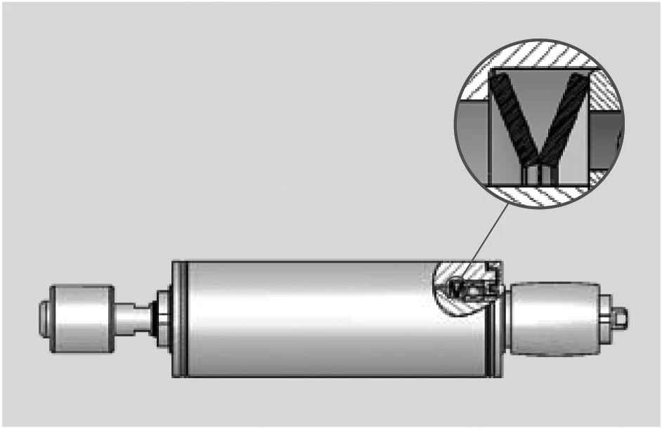
With every ball bearing there is radial play so it may function correctly.
This radial play or clearance can cause considerable noise at high speeds. In many cases it is possible to achieve a quiet running bearing assembly by the use of a suitable disc spring to apply an axial load to the bearing.
Similarly, the springs can be used to accommodate the build up of tolerances or thermal movements within the assembly.
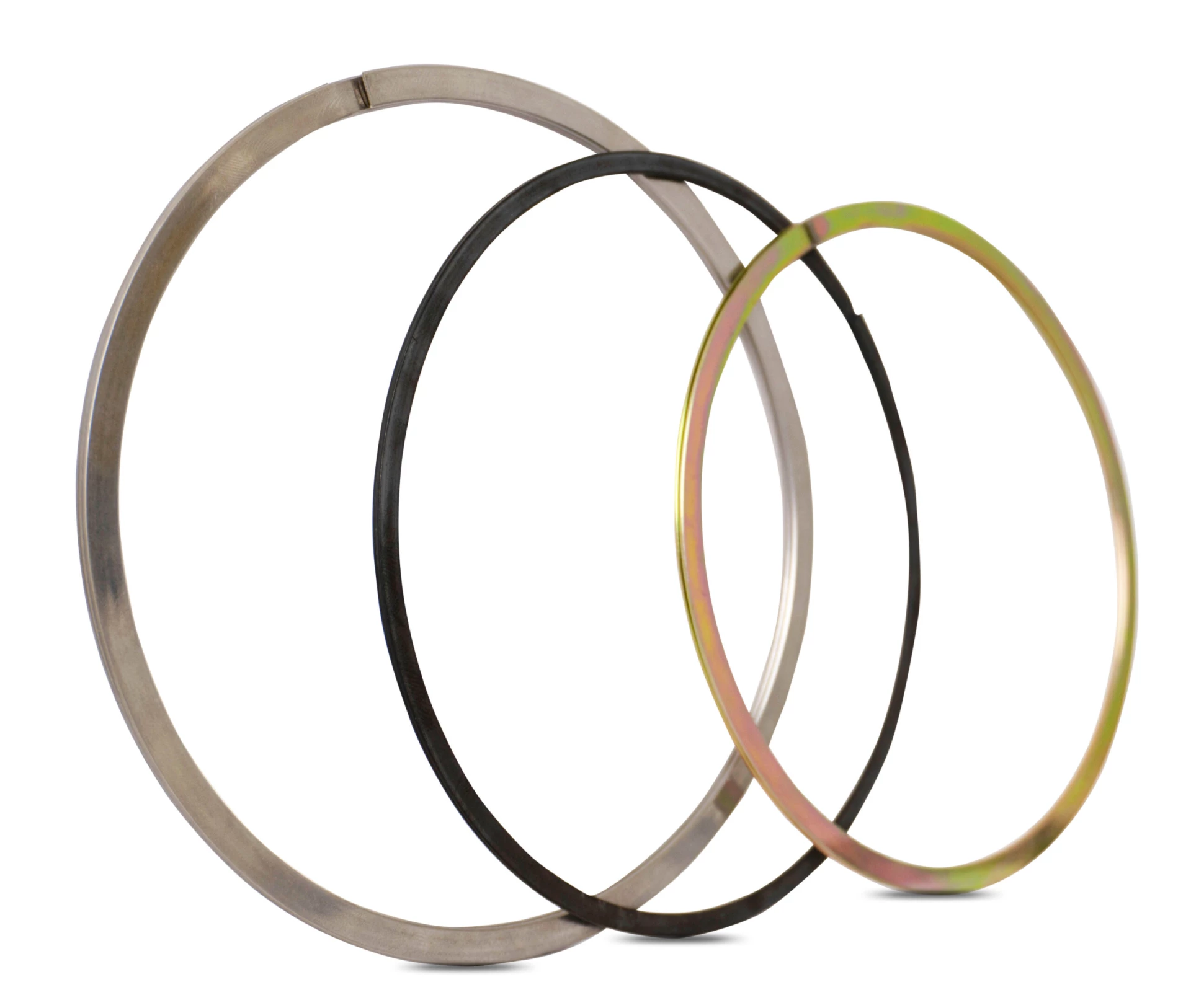
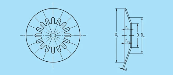
In addition to the normal range ‘slotted’ springs are available up to a diameter of 95mm. This special design generates very small loads and will accommodate large deflections.
The load and dimension tolerances of DIN 2093 do not apply to this type of disc spring.
For the dimensions of ‘K’ Disc springs click here.
The inclusion of slots on either the inner or outer diameter creates a lever which works on the unslotted portion of the spring. This has the effect of reducing the spring load and increasing the deflection (figure 39).
Figure 39 – click to enlarge
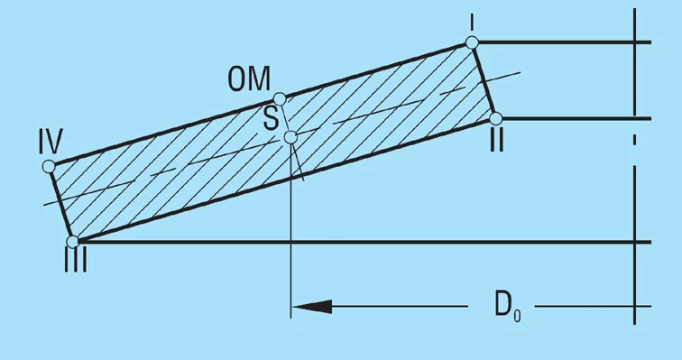
By the use of a trapezoidal cross-section it is possible to equalise the stresses on the spring upper and lower surfaces. The advantageous tensile stresses on the lower surface contribute to a better fatigue life. The equal compressive stresses at points ll and lll to give the optimum fatigue life can also be achieved with a rectangular cross-section spring if the ratios δ and ho/t are correctly chosen. In this regard therefore, the trapezoidal cross-section offers no advantages. Compared with a standard spring having a similar angle on the top surface, a trapezoidal spring will give less deflection. This can be increased by including intermediate rings, but these will also increase the overall stack length and require more space.
Figure 40 – click to enlarge
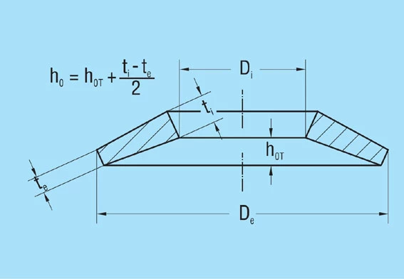
The main advantage of the trapezoidal cross-section disc spring is the ability to limit the stroke without additional parts. It is therefore possible to design a spring which is relatively fatigue free over the complete deflection range with relatively little increase in load towards the end of the stroke.
With the same installation space and under consideration of the permissible stresses, no more favourable spring data (more force or more deflection) can be achieved with disc springs with a trapezoidal cross-section than with springs with a square cross-section.
These few advantages and the higher manufacturing costs are the reasons why the trapezoidal disc spring is of no practical importance today.