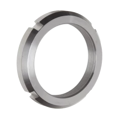
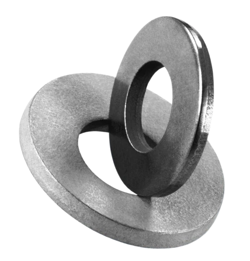
Schnorr Disc Springs
With more than 100 years experience of disc spring engineering, Schnorr have long been a key partner to IEC. Together, we have secured specification for a wide range of specialist applications into multiple industries, including aerospace, automotive, marine and rail. If your business needs Schnorr disc springs, get in touch.
Schnorr Disc Springs
Maximum load, minimal space
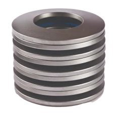
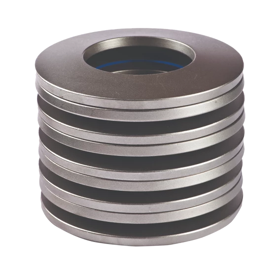
Schnorr disc springs are conical discs which can be loaded along their axis either statically or dynamically. The loads are normally applied to the upper inner edge and the lower outer edge. Either a single spring or a stack or springs can be used. Disc springs are versatile and are used in many manufacturing and plant applications.
Please take a look at the full catalogue of Schnorr Disc Springs.
Benefits of IEC's Schnorr Disc Springs
- Space saving - high spring forces with small deflection
- No permanent deformation or fatigue under normal loads
- Load/deflection curves of straight, regressive or progressive character according to design requirements
- Largely self-damping particularly with parallel stacking, giving good shock absorption and energy dissipation
- Load/deflection curves of straight, regressive or progressive character according to design requirements
- Long service life


Markets
IEC have a range of mechanical solutions to suit a broad spectrum of markets and applications, from aerospace to skateboards.
Markets
IEC have a range of mechanical solutions to suit a broad spectrum of markets and applications, from aerospace to skateboards.
Markets
Molestie nunc non blandit massa. Iaculis nunc sed augue lacus. Malesuada nunc vel risus commodo. Dui id ornare arcu odio ut sem nulla pharetra.
Case Studies
Disc Spring Applications

Product:
Application:
Challenge:
Solution:
Product:
Application:
Challenge:
Solution:

Product:
Application:
Challenge:
Solution:

Product:
Application:
Challenge:
Solution:

Download technical documents and brochures.
Keep up to date with the latest product and technical information from IEC and its international supply partners.
Schnorr Disc Springs Catalogue
Schnorr Disc Springs Introduction
- ABB
- Airbus
- BAE Systems
- Bosch
- Daimler Chrysler
- Siemens
- TATA Steel
Why Choose Schnorr Disc Springs for Your Applications?
Established in 1908, Schnorr has pioneered the production and application of high-quality Schnorr disc springs. These innovative springs are designed to meet the most demanding requirements across various industries, offering unmatched reliability and performance.
Natural developments in their product range include bearing preload springs and safety washers, both of which benefit from the same meticulous engineering and quality standards.
With more than 100 years of experience, Schnorr products are now used in a wide range of demanding applications in the aerospace, automotive, electrical, marine, and rail industries. Their extensive customer base includes prestigious companies such as:
- ABB
- Airbus
- BAE Systems
- Bosch
- Daimler Chrysler
- Siemens
- TATA Steel
Schnorr disc springs are manufactured to EN16983 and EN16984 standards using high-quality spring steels. When needed, heat or corrosion-resistant materials such as Inconels and Nimonics are employed to ensure durability and performance in harsh environments.
Key Features and Benefits of Schnorr Disc Springs
- Wide Range of Sizes: The standard range includes approximately 250 sizes with outer diameters from 6 to 250mm, catering to diverse application needs.
- Material Excellence: Manufactured from premium spring steels and special alloys for high performance under dynamic loadings.
- Expert Engineering: Schnorr’s deep understanding of the stresses in a disc spring ensures that their products are particularly suitable for dynamic loadings—a common failure area for less well-made springs.
- Custom Solutions: With over 12,000 special variants produced (the largest 80mm thick), Schnorr offers tailor-made solutions to meet exact customer specifications, particularly for applications requiring long service life combined with dynamic stress.
Schnorr’s engineering expertise enables them to provide solutions tailored to specific requirements, ensuring long-lasting performance and reliability. Their commitment to quality and innovation has made them a trusted partner for leading companies worldwide.
For further information on how Schnorr disc springs can enhance your applications, contact our team of experts at IEC Ltd.
ALLOWABLE STRESS FOR STATIC OR QUASISTATIC LOADS
DISC SPRING FEATURES
- Space saving – high spring forces with small deflection
- Load/deflection curves of straight, regressive or progressive character according to design requirements
- Spring stack characteristics can be altered by the simple removal or addition of individual spring
- Largely self-damping particularly with parallel stacking, giving good shock absorption and energy dissipation
- No permanent deformation or fatigue under normal loads
- Long service life
CHECKLIST FOR DISC SPRING DESIGN
Due to the relatively simple geometrical shape the complexity of disc springs in production and application is very often underrated. There are possibilities for mistakes in outlining a disc spring solution, which inevitably cause faulty design or even failures later on. Then it is very difficult to find better substitutes, because most of the times the installation space is fixed.
With a correct design these problems are easy to avoid. The main difficulty is to realise these in the design stage to get an optimum disc spring solution.
Since for most of the designers the disc spring is not daily bread and to many the rules for disc spring design are little known, the most important aspects are summarised here.
Spring Force
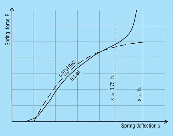
The calculation of the force of a disc spring is based on a model by Almen and Laszlo. Its accuracy in the usable range of the character line of the spring is very good. Yet there is a slow rise at the beginning of the measured load/reflection curve, because disc springs never are perfectly symmetrical. They so to speak have to be pressed even. Also the spring force rises in the last part of the load/deflection curve more than calculated, when the spring is loaded in between two parallel planes, since the leverage changes due to the never ideally even surfaces.
Static Loading
In the design of a new disc spring a certain stress level should not be surpassed for static loading. The maximum allowable limit is given by the reference stress σom. Its value should not exceed the value of the tensile strength Rm of the material to avoid plastic deformations of the spring, i.e. setting losses.
Dynamic Loading
Most of the disc springs only can bear a limited dynamic load. The life time depends on the load span as well as on the load level. The number of cycles, which is to be expected under a certain load condition, can be estimated from fatigue diagrams. It is also necessary to reload disc springs in a dynamic application to at least 15% to 20% of their maximum deflection, to avoid compression-tension alternating stresses in the beginning of the deflection range of the spring.
Stacking
Disc springs can be stacked “face to face” (series arrangement), which means their deflections add up, or they can be stacked in the same sense (parallel arrangement), then their forces add up. The latter induces increased friction and a stronger hysteresis effect. Thus the force in loading direction is higher and in unloading direction lower than the calculated force. Applying suitable lubrication (MoS2 containing grease) can reduce the hysteresis effect. The various possibilities of stacking disc springs can be combined in a stack. Different types of stacking in one spring stack can be used to generate a progressive character line. It is necessary to pay attention to the weaker parts in a combined stacking though, because these normally are pressed flat quite fast, which is not allowed in dynamic loading. If necessary a deflection limitation has to be provided.
Guide
The surface of guide elements is dynamic disc spring applications always has to be harder than the disc springs themselves. A minimum of 55 HRC is advisable, otherwise the surfaces can be damaged. This again causes uneven movement during the deflection of the spring. The characteristics will be changed and even fatigue cracks can occur. Wrong guide clearance also can change the dynamics of loading in a detrimental way.
Stack Length
Friction and other influences make a spring stack move unevenly. It deflects more on the side of the loading. This effect usually can be neglected for a “normal” spring stack, but not for long stacks. Therefore the length of a spring stack should not exceed three times the value of the outer diameter. If it is longer, the stack can be stabilised by dividing it with guide washers, which as a rule of thumb should have a thickness of at least one and a half times the guide diameter.
Material
The best material for disc springs is standard spring steel. It is always used as long as there are no particular circumstances, which may necessitate a special material. In general special materials have a lower tensile strength and most of the times a different Young’s modulus compared to the standard spring steels. Therefore springs out of these materials generally cannot be designed with the same free height, which means that the spring forces are lower.
Temperature
The different materials have different temperature ranges. Too high temperatures may have a tempering offset, which again results in a loss of force and, in extreme cases, in plastic deformation (setting losses).
Corrosion
Disc springs can be protected against corrosion either by suitable coatings or by using corrosion resistant materials. Such materials are only available in a limited variety of thicknesses. Also almost all high alloy steels may show stress corrosion cracking at high working stresses.
Hydrogen Embrittlement
During the application of certain chemical or electrochemical processes (such as galvanic coating) hydrogen can get in to the material and can cause delayed brittle fractures. This cannot be avoided entirely by thermal treatment. Thus processes, which do not bear this risk, are to be preferred.
STANDARDS FOR DISC SPRINGS
- DIN 2092 Disc Springs, calculation and;
- DIN 2093 Disc Springs, dimensions and quality specifications
THE SCHNORR PRODUCTION PROGRAMME
DIAGRAM OF A DISC SPRING
Symbols | Unit | Designation |
De | mm | Outside diameter |
Di | mm | Inside diameter |
Dw | mm | Diameter at the root of slots in a disc spring |
Do | mm | Diameter of centre of rotation |
E | N/mm2 | Young’s modulus |
F | N | Spring force of a single spring |
F1, F2, F3 | N | Spring force for deflections s1, s2, s3 |
Fc | N | Calculated spring force of a single spring when flat |
Fges | N | Spring force of a spring set or stack |
ΔF | N | Force lost in setting |
K1, K2, K3, K4 | Constants for calculations | |
LO | mm | Unloaded length of the spring stack or spring sets |
L1, L2, L3 | mm | Length of the loaded spring stack or spring set for forces F1, F2, F3 |
Lc | mm | Calculated length of the spring stack or set when springs are flat |
N | Number of cycles to failure | |
R | N/mm | Spring rate |
W | N/mm | Spring work |
ho | mm | Cone height of an unloaded single spring (calculated ho = lo – t) |
ho‘ | mm | Cone height of an unloaded spring with reduced thickness t’ (and contact flats, calculated ho=lo– t) |
i | No. of single springs or sets in series in a stack | |
lo | mm | Height of an unloaded spring stack |
n | No. of parallel springs in a set | |
s | mm | Deflection of a single spring |
s1, s2, s3 | mm | Deflections relative to loads F1, F2, F3 |
sges | mm | Deflection of a spring set or stack |
t | mm | Thickness of individual |
t’ | mm | Reduced spring thickness for springs with contact flats (group 3) |
WM, wR | Friction factors | |
δ= De/Di | Diameter ratio | |
µ | Poisson’s ratio (for spring steel = 0.3) | |
σ | N/mm2 | Calculated stress |
σOM, σl, σll, σlll, σlv | N/mm2 | Calculated stress at points OM, I, II, III and IV as per figure 1 |
σo | N/mm2 | Calculated maximum stress for springs with dynamic loads |
σu | N/mm2 | Calculated minimum stress for springs with dynamic loads |
σh | N/mm2 | Stress range for the working stroke of dynamically loaded springs |
σO | N/mm2 | Maximum stress for fatigue resistance |
σU | N/mm2 | Minimum stress for fatigue resistance |
σH = σ0 – σU | N/mm2 | Permissible stress range for fatigue resistance |
Schnorr Disc Spring Size Range
Standard Material
- Disc Springs Ø 6 – 18mm
- Disc Springs Ø 20 – 35.5mm
- Disc Springs Ø 40 – 80mm
- Disc Springs Ø 90 – 150mm
- Disc Springs Ø 160 – 250mm
Corrosion Resistant
- Disc Springs Ø 6 – 18mm – Stainless Steel X10CrNi 18-8 (DIN 1.4310)
- Disc Springs Ø 20 – 31.5mm – Stainless Steel X10CrNi 18-8 (DIN 1.4310)
- Disc Springs Ø 34 – 90mm – Stainless Steel X10CrNi 18-8 (DIN 1.4310)
Heat Resistant
- Disc Springs Ø 6 – 20mm – Stainless Steel X39CrMo 17-1 (DIN 1.4122)
- Disc Springs Ø 23 – 50mm – Stainless Steel X39CrMo 17-1 (DIN 1.4122)
- Disc Springs Ø 56 – 200mm – Stainless Steel X39CrMo 17-1 (DIN 1.4122)
- Disc Springs Ø 20 – 71mm – Stainless Steel X22CrMoV 12-1 (DIN 1.4923)
- Disc Springs Ø 80 – 250mm – Stainless Steel X22CrMoV 12-1 (DIN 1.4923)
OTHER SIZES OF DISC SPRING
Bearing Preload Type K
Inch Dimensions Type Z
Basic Calculation
- Calculation for a single spring
- Equations for calculations
- Disc springs without contact flats
- Disc springs with contact flats and reduced thickness
- Disc springs of special material
- Spring parameters for dimensions and calculation
- Characteristics of a single spring
- Calculation examples
CALCULATION FOR A SINGLE SPRING
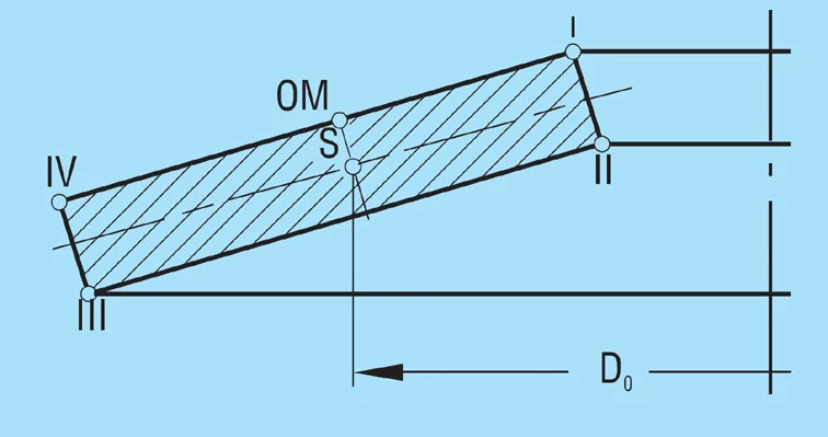
The calculations of Almen and Laszlo assume that a spring flank rotates around a centre of rotation during deflection, placed in the centre of the spring flank at diameter Do.
Formula 1

The rotation of the cross section is the reason for the various stresses and the spring effect.
The calculations assume that Young’s modulus ‘E’ remains linear for the material, the spring cross-section is rectangular with sharp corners and the spring remains in one plane during deflection. The load is applied at points l and lll. There is residual stress in the spring after being manufactured and heat treated and can be ignored.
Although today there are more accurate methods of calculation, there is no reason to abandon the simple and convenient formulas of DIN 2092. For standard dimensions they produce values which correspond well to the measured results.
Figure 2 – click to enlarge
EQUATIONS FOR CALCULATION
These are valid for all disc springs.
Characteristics
Formula 2

Formula 3
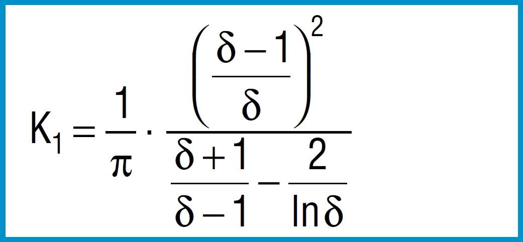
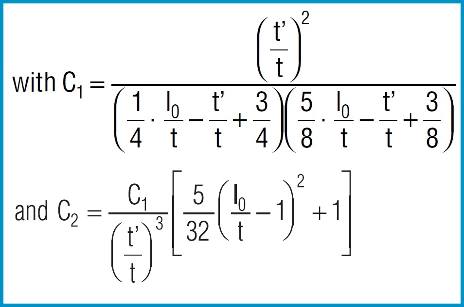
Formula 4

Formula 5

Formula 6

Spring Force
Formula 7

For disc springs manufactured to group 1 and 2 K4 = 1:
Formula 8a

For disc springs manufactured to group 3 with contact flats and reduced thickness, t’ and ho’ must be used
(ho’=lo-t’):
Formula 8b

Young’s modulus ‘E’ is virtually independent of the heat treatment condition and tensile strength of the material.
For steel springs with dimensions in accordance with DIN 2093, formula 7 provides values which correspond closely to the measured values.
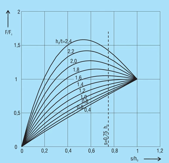
The force of a disc spring does not increase linearly with the deflection, but is always regressively curved. Its pitch, i.e. the rate, decreases with increasing stroke. The ratio of curvature is determined exclusively by the ratio ho/t, as can be seen in figure 3.
Figure 3 – click to enlarge
Stress Calculations
Formula 9

Formula 10

Formula 11

Formula 12

Formula 13

Here
4E= 905 495 N / mm2
1 – µ2
also applies to spring steel. Positive values are tensile stress and negative values are compressive stress. It is important to remember that this the calculated stress is a normal value and that the actual stress is considerably lower, as it is considerably influences by the ever-present internal stress.
Spring Rate
Through differentiation of the spring load F in accordance with the reflection s, the following formula is obtained for spring rate R:
Formula 14

The spring rate between any two adjacent points F1,s1an F2, s2can be approximated by means of the following simple formula:
Formula 15

Spring Work
The work done by a disc spring can be obtained by integrating formula 7 for the load F according to the deflections:
Formula 16

For a limited area of application it can be integrated between the two deflections s1and s2.
DISC SPRINGS WITHOUT CONTACT FLATS
DISC SPRINGS WITHOUT CONTACT FLATS
For disc springs without contact flats K4 = 1 and ho = lo – t. This applies to all disc springs in production groups 1 and 2, i.e. with a thickness of up to 6.0mm.
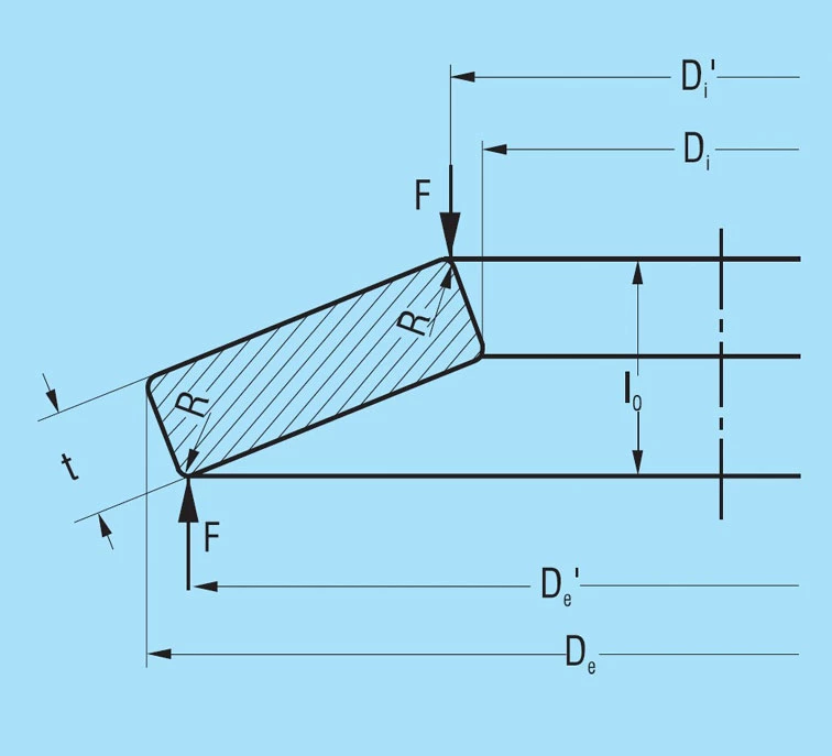
Because of the rectangular cross-section with rounded corners, as is specified for springs in groups 1 and 2, the application of load in practice always takes place via slightly shortened lever arms (see figure 4). Due to the h/H tolerance for the outer and inner diameters, the lever arms are shortened even further. This results in an increase in the spring load by the factor:
De – Di
De’ – Di’
in virtually all springs compared to the values calculated with formula 7.
These conditions take the standard DIN 2093 into consideration in that the thickness tolerances towards the minus side are clearly larger than towards the plus side. Therefore, we manufacture all springs with a slightly reduced disc thickness. This reduction in the lever arm length is also an explanation for the fact that the permissible deviations for the spring loads for groups 1 and 2 are considerably larger toward the plus than the minus side.
DISC SPRINGS WITH CONTACT FLATS AND REDUCED THICKNESS
For disc springs with a thickness of more than 6.0mm, DIN 2093 specifies small contact surfaces at points l and lll in addition to the rounded corners. Figure 5 shows a schematic cross-section of a spring in group 3 as per DIN 2093. The corresponding springs of our factory standard are also manufactured in the same manner.
Figure 5 – click to enlarge
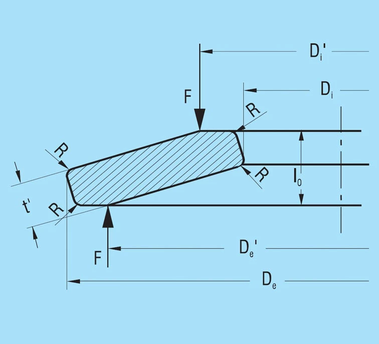
These contact flats improve definition of the point of load application and, particularly for spring stacks, reduce friction at the guide rod. The result is a considerable reduction in the lever arm length and a corresponding increase in the spring load. This is in turn compensated for by a reduction in the spring thickness from t to t’.
When calculating disc springs with contact flats and reduced thickness, the factor K4 must be calculated using formula 6, and t replaced with t’ and ho with ho’ = lo – t’ in the equations 7 to 16.
The reduced thickness t’ is specified in accordance with the following conditions:
- The overall height lo remains unaltered
- The width of the contact flats is to be approximately 1/150 of the outside diameter
- The spring load for a reduced thickness spring must be the same at s = 0.75 ho as for an unreduced spring
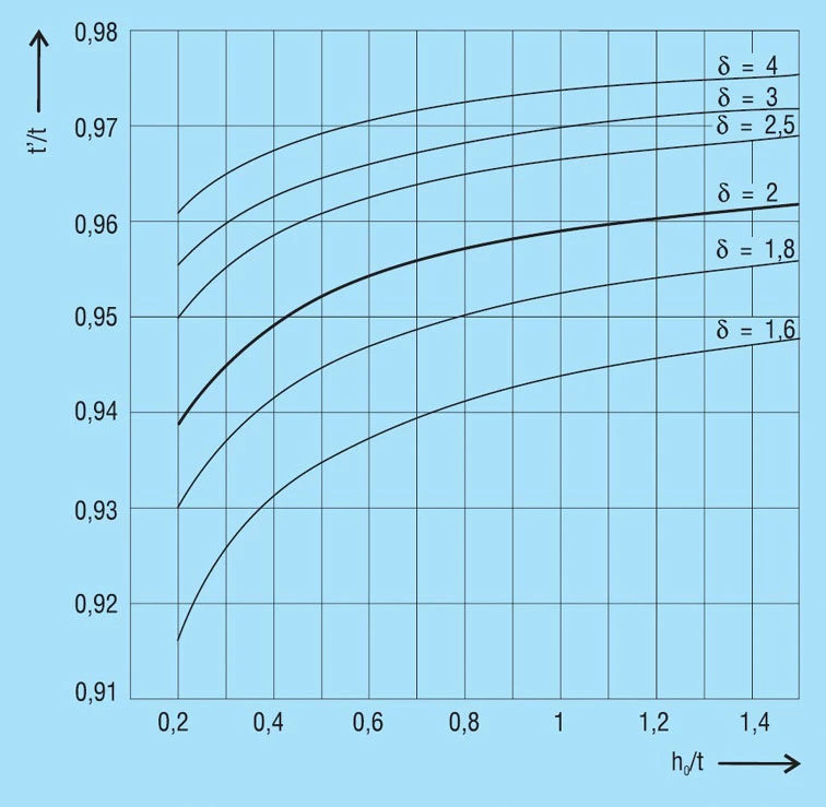
The dimension t’ is specified for those discs springs contained in DIN 2093. The mean factor t’/t is:
| Series | A | B | C |
| t’/t | 0.94 | 0.94 | 0.96 |
For other springs the factor for t’/t is dependent on the dimensional ratio δ and ho/t from figure 6. The curves were calculated for disc springs with δOM = -1600N/mm2. For springs with different stress sOM, we would ask you to contact us on 01202 339559.
As the overall height is not reduced, springs with reduced thickness inevitably have an increased flank angle and a greater cone height ho’ than springs of the same nominal dimension without reduced thickness. Therefore, the characteristics curve is altered and becomes more curved. Figure 7 shows the characteristic curves for springs of the series A, B and C as per DIN 2093 with and without contact flats and reduced thickness.
Figure 6 – click to enlarge
DISC SPRINGS OF SPECIAL MATERIAL
When special materials are used with different ‘E’ moduli and Poisson’s ratio µ, it is recommended that the corresponding ‘E’ modulus is used, but that the value of 0.91 for 1-µ2 be retained.
Formula 7

This is justified with the fact that formula 7 for steel with E = 206 000 N/mm2 and µ = 0.3 provides loads 8 – 9% higher, however this is more or less balanced out again by radii and cross-section related shortening of the lever arm.
SPRING PARAMETERS FOR DIMENSIONS & CALCULATION
Disc springs are determined essentially by the following three parameters:
δ = Outside diameter De
Inner diameter Di
Ho/t =
Cone height Io – t
Disc thickness t
De/t = Outside diameter De
Disc thickness t
If at all possible, the parameters above should be within the following values:
δ = 1.75…2.5
ho/t = 0.4…1.3
De/t = 16…40
For smaller values δ, smaller values of ho/t and De/t also apply and vice-versa.
For steel springs with dimensions within these limits, formula 7 can be used without restriction. For very thin disc springs (De/t > 50) the formula results in spring forces which are too high.
Formula 7

CHARACTERISTICS OF A SINGLE SPRING
The value ho/t determines the amount of curvature of the spring characteristics (figure 3). For ho/t < 0.4, thecharacteristics is almost linear, as the value ho/t increases, the curve becomes more regressive. At ho/t = √2 the curve has a nearly horizontal segment (at s = ho it has a horizontal tangent). This means that springs can be developed with an almost horizontal characteristic, which gives very little load increase with deflection. However, this type of spring with ho/t > 1.3 is not suitable for long spring stacks, as individual springs within the stack may move unevenly and be overloaded. As a result, such springs should only be used alone.
Figure 3 – click to enlarge
Figure 8 – Click to enlarge
On the other hand, the force of the flattened disc spring increases linearly. If, for example, a spring calculation cannot predict this in a satisfactory manner, then a first step in the form of a change in the free height may already produce the desired load/deflection diagram. Here, however, the permissible stress must be observed, as these increase with increasing cone height ho.
At ho/t > √2, the spring force reaches a maximum and then decreases again. In some cases the decreasing segment of the curve is utilised. Under certain conditions the spring must be loaded beyond the flat position, for which certain design conditions must be given (figure 9).
Figure 9 – Click to enlarge
For the normal arrangement of disc springs a progressive increase in the spring force occurs at deflections of s > 0.75 ho which deviates from the calculated value. This results from the shift in the load points to smaller lever arms, because the disc springs roll on each other or on the abutments. Therefore, it is recommended that only approx. 75 to 80% of the spring deflection is utilised. For this reason, the spring force is only indicated at s ≈ 0.75 ho in DIN 2093 (figure 10).
Figure 10 – Click to enlarge
Basic Calculation Examples
The ‘life lines’ also allow the fatigue life to be estimated for various working strokes. In spite of this we show several examples of the calculation and checking of disc springs below.
Example 1: Checking fatigue life of a disc spring
Given:
Spring 45 x 22.4 x 1.75; lo = 3.05mm (figure 11)
Preload F1 = 1580N
Final Load F2 = 2670N
Frequency f = 1000/min
To be determined:
Is the stress within the acceptable range – what is the estimated fatigue life.
Solution:
From the tables of disc springs we can obtain the following data:
s/ho s[mm] F[N] s[N/mm2]
0.25 0.325 1524 433
0.5 0.650 2701 814
0.75 0.980 3659 1148
1.0 1.300 4475 1421
With the help of these four points the load and stress relative to the deflection may be drawn.
Figure 11 – click to enlarge
Disc spring 45 x 22.4 x 1.75; lo = 3.05 mm
The following values may be obtained from the diagram (figure 12):
S1 = 0.34mm, S2 = 0.64mm
σu = 450 N/mm2
σo= 804 N/mm2
From the fatigue diagram for group 2 springs figure 19, we obtain σu 450 N/mm2 with a maximum stress of σ0= 920 N/mm2. Therefore the spring is fatigue resistant as σo < σ0.
Figure 12 – click to enlarge
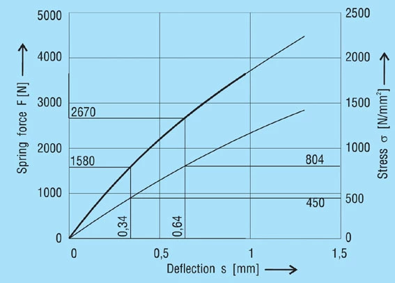
Diagram for spring 45 x 22.4 x 1.75 mm, lo = 3.05 mm
Example 2: Disc spring with a high ho/t ration
Given:
Guide diameter 30mm
Installed length l1 = 4,9mm
Preload F1 = 2000 N min.
Working defl. s2 – s1 = 1.05mm
Spring load F2 = 2500 N max.
Required:
Suitable disc spring dimensions
Solution:
Spring inside diameter Di = 30.5mm
Spring outside diameter De = 60mm (selected because of the favourable De/Di ratio)
Because of the very small load range and the small installed length only a spring with a high ho/t ratio is suitable.
Selected:
Disc spring 60 x 30.5 x 1.5mm (figure 13); lo = 3.5mm ho/t = 1.333; δ = 1.967
Calculation:
First the factors are calculated using formula 3, 4 and 5:
K1 = 0.688
K2 = 1.212
K3 = 1.365
Figure 13 – click to enlarge
Disc spring 60 x 30.5 x 1.5 mm
The stress σOM can be checked using formula 9: σOM = -1048 N/mm2.
This value lies well under the limit of -1600 N/mm2, the spring will therefore not set. Now the spring loads can be calculated to formula 8a, preferably for the 4 deflections s = 0.25 ho, s = 0.5 ho, s = 0.75 ho and s = ho.
One obtains the following values:
s/ho s[mm] F[N]
0.25 0.5 1338
0.5 1.0 2058
0.75 1.5 2367
1.0 2.0 2469
With these 4 points the spring diagram can be drawn.
Figure 14 – Click to enlarge
Diagram for spring 60 x 30.5 x 1.5 mm, lo = 3.5 mm
One can read F1 = 2100 N s1 = 1.05mm
and for F2 = 2400 N s2 = 1.61mm
Deflection s2 – s1= 0.56mm
The deflection of a single spring is not sufficient, therefore two in series must be used.
This arrangement gives:
Unloaded length Lo=7.0mm
Preloaded length L1=4.90mm
Preloaded deflection s1=2.1mm
Preload F1=2100N
Deflection s2=s1+1.05=3.15mm
Final load F2=2390N
To check the fatigue life we must use the stresses at s1 = 1.05 and s2 = 1.575mm. Figure 17 shows that point lll is the dominant one, this gives:
s1: σu = 843 N/mm2
s2: σu = 1147 N/mm2
By utilising the fatigue life diagram in figure 19 we can see that the expected life will be in the order of 1,000,000 cycles.
Example 3: Calculation of a disc spring with contact flats
Given:
Disc spring 200 x 82 x 12mm; lo = 16.6mm
Ho = 4.6mm; δ = 2.439; ho/t = 0.383
Required:
The spring characteristics and the stresses σll and σlll.
Although this spring is to our works standard we show below how the calculations are made and results can be checked in the disc springs dimension tables.
From the formula 3 to 5 we first calculate the constants K1 to K3:
K1 = 0.755
K2 = 1.315
K3 = 1.541
The static design can be checked by the calculation of σOM, the reduced thickness is not considered and we use the values of t and ho. This gives:
σOM = -1579 N/mm2
As the acceptable value for σOM is 1600 N/mm2, the spring is correct. From figure 6 and considering d and ho/t the reduction factor t’/t can be obtained:
t’/t = 0.958
Therefore t’ = 11.5mm and ho’ = 5.1mm. Constant K4 can be calculated from formula 6: K4 = 1.0537.
Figure 15 – Click to enlarge
Disc spring 200 x 82 x 12 mm
Figure 16 – click to enlarge
Spring force and stresses for spring 200 x 82 x 12 mm, t’ = 11.5 l0 = 6.6 mm
Now from formula 8b, 11 and 12 the spring force and both stresses can be calculated.
s/ho s[mm] F[N]
σll
[N/mm2]
σlll
[N/mm2]
0.25 1.15 66924 416 389
0.5 2.3 127191 890 747
0.75 3.45 182838 1421 1072
1.0 4.6 235503 2011 1366
With this spring the greater values of stress are on the inner diameter which should be used. Finally the value of the stress σOM for the reduced thickness can be checked:
σOM’ = σOM . K4 . t’/t
σOM’ = -1595 N/mm2
DESIGN AND OPERATION LIMITS
- Allowable stress for static or quasistatic loads
- Permissible stress for dynamic loads
ALLOWABLE STRESS FOR STATIC OR QUASISTATIC LOADS
Static Design
Static or rarely changing loads exist when:
Disc springs carry only static, non-changing loads.
Disc springs are subject to occasional load changes at greater time intervals and less than 10,000 load cycles during the planned service life.
Disc springs are normally designed with an overall height lo, so that they can be flattened under static or rarely changing loads without the overall height lo reducing by more than the permissible tolerance. The stress σOM at point OM defined in formula 9 applies here.
Permissible Stress
Plastic deformations occur, when the stresses in certain areas exceed the yield strength. References stress is σOM. Its value should not exceed the tensile strength Rm of the material used. For spring steel as per DIN EN 10132-4 and DIN 17221 the tensile strength is Rm≈1600 N/mm2. For other materials, the respective applicable yield point values must be used. Disc springs as per DIN 2093 and our factory standards listed in the disc spring dimension tables were designed according to an earlier method using the stress at point l.
For this reason, some of these springs exceed the permissible stress at the point OM. As these springs have been manufactured for years with this overall height lo, we have not changed the height. With these types of springs there is the possibility of slight setting in use.
PERMISSIBLE STRESS FOR DYNAMIC LOADS
Dynamic loads occur in disc springs when the load continuously changes between a preload deflection s1 and a deflection s2. Under the influence of a change in stress of σh, dynamically loaded disc springs can be divided into two groups by service life (see also DIN 50100):
Disc springs for longer life. These disc springs are intended to withstand load cycles of a least 2 . 106 and more without breaking. If a considerably longer life is required, please contact us. It may be that only an endurance test can provide exact information.
Disc springs with a limited service life. These disc springs are intended to achieve a limited number of load cycles in the range between 104 < N < 2 . 106 before failure.
Critical Stress Affecting Dynamic Failure
For disc springs carrying dynamic loading, the calculated tensile stress on the underside of the spring are the determining factors, as fatigue cracks always start here. In dependency on the dimensional ratio δ = De/Di and ho/t and the relative deflection s/ho, the largest stress range σh may occur at both point ll and lll is decisive can be derived figure 17 for springs with and without contact flats.
Figure 17 – click to enlarge
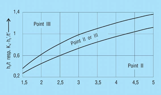
We recommend calculating the stress for both points using formulas 11 and 12. Use the larger value to determine fatigue life using the applicable diagrams (figure 18 – 20).
Minimum Preload to Prevent Superficial Cracks
After head treatment all discs springs are going to be scragged or pre-stressed, which causes a plastic deformation in the region of cross-sectional point l. This results in residual tensile stress at this point in the unloaded spring. When loaded there is then a change from tensile to compressive stress which can result in the formation of cracks during dynamic loading. To avoid these the tensile stress must be balanced out by applying a suitable pre-stress. Therefore, dynamically loaded disc springs should be preloaded to at least s = 0.15 to 0.20 ho.
Permissible Stress
The stress calculated for the working range of the spring is compared with the fatigue diagrams in figure 18 – 20. These provide standard values of the permissible stress range σH for N > 2.106, N = 5.105 and N = 105 load cycles in dependency on the minimum stress σU for dynamically loaded, non-shot-peened disc springs. Intermediate values for other load cycles can be estimated.
A fatigue diagram is indicated for each of the 3 manufacturing groups as per DIN 2093. These groups are divided by the disc thickness as follows:
Group 1: t less than 1.25mm
Group 2: t = 1.25 to 6mm
Group 3: t over 6 to 14mm
These diagrams were developed from laboratory tests on test machines with an even sinusoidal load by means of statistical evaluation, whereby a survival rate of 99% was assumed. This means that for a large enough sample a failure rate of 1% can be expected due to fatigue.
The diagrams are applicable to single springs and spring stacks with up to 10 single springs stacked in series, operating at room temperature with hardened and perfectly finished inner or outer guides and minimum preload deflection of s1 = 0.15 to 0.20 ho.
Figure 18 – click to enlarge
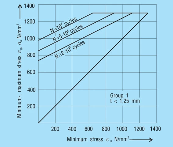
It should be noted that in practice the type of loads applies in many cases deviates from a nearly sinusoidal frequency. In the case of an impact-type load cycle and as the result of natural frequencies, the actual material loading in considerably greater than the calculated value. The values of the diagrams may only be used for these types of loading under inclusion of the appropriate safety factors.
For disc springs of materials other than those specified in DIN 2093, for spring stacks with more than 10 or with multiply parallel-stacked individual springs, and in the case of unfavourable influences of a chemical or thermal nature, sufficient data to predict fatigue are not yet available. In such cases additionally safety factors must also be applied we recommend you contact us.
Figure 19 – click to enlarge
Figure 20 – click to enlarge
POSSIBLE COMBINATIONS
- Possible combinations of a single spring
- Single-series spring stack (series stacking)
- Parallel springs in spring sets (parallel stacking)
- Spring stack of parallel sets in series
- Progressive spring characteristics

POSSIBLE COMBINATIONS OF SINGLE SPRINGS
POSSIBLE COMBINATIONS OF SINGLE SPRINGS
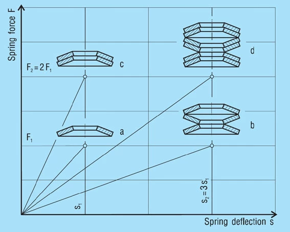
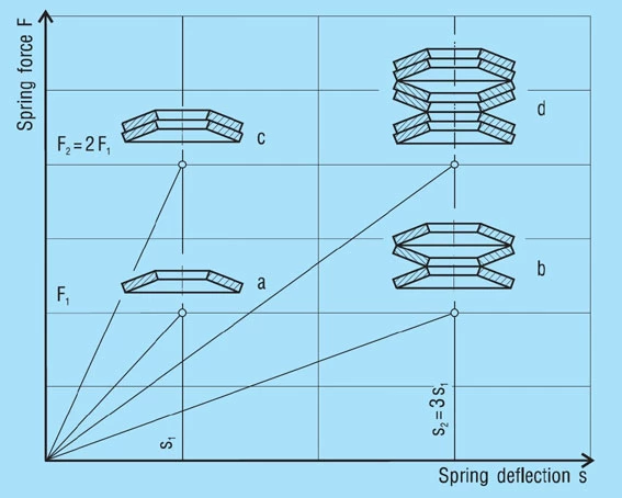
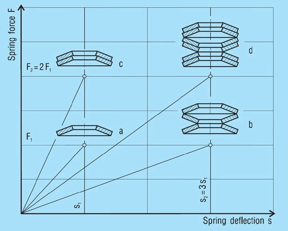
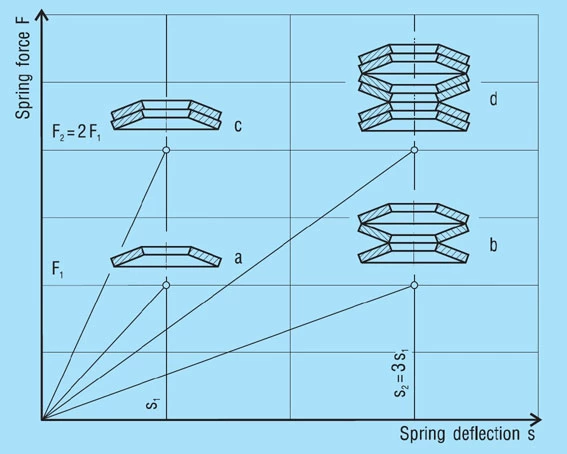
The shape of the disc spring as a conical disc allows single springs to be combined in different ways. As a result, the characteristics of a spring combinations can be varied in almost any way desired and adapted to the requirements. In principle the following possibilities exist (figure 21):
- Single-series spring stack (series stacking)
- Parallel springs in spring sets (parallel stacking)
- Spring stack of parallel sets in series
The determination of the characteristic for assembled disc springs stack is based on the characteristic of the single (figure 21 – a).
Figure 21 – click to enlarge
Stacks in Series
A stack of ‘i’ springs in single series (figure 21 – b) results in the following without considering friction:
Spring Load
Formula 17

Spring Deflection
Formula 18

Unloaded Stack Length
Formula 19

Only the deflection is multiplied by the number of springs in series, not the load.
SHOT PEENING
A set of ‘n’ single springs in parallel (figure 21 – c) results in the following without considering friction.
Spring load
Formula 20

Spring Deflection
Formula 21
Unloaded Stack Length
Formula 22

In this case the spring load must be multiplied by the number of springs in parallel, where as the deflection remains as for a single spring.
For springs in Group 3 with contact flats and reduced disc thickness, t must be replaced with t’ in formula 22.
STACKS FROM SPRING SETS
This is the combination of parallel sets in series (figure 21 – d). For ‘i’ sets in series and ‘n’ springs in parallel following results without considering friction:
Spring load
Formula 23

Spring Deflection
Formula 24
Unloaded Stack Length
Formula 25

With this arrangement the spring load is proportional to the number of disc springs in parallel, while the deflection in proportional to the number of sets. In formula 25 t must be replaced with t’ if necessary.
Figure 21 – click to enlarge
PROGRESSIVE SPRING CHARACTERISTICS
PROGRESSIVE SPRING CHARACTERISTICS
In many cases it is a requirement that the spring load increases progressively as the deflection increases, i.e. the rate of the characteristic increases instead of (as it is typical for disc springs) decreasing (figure 22). Such characteristic curves can be achieved in various ways.
Figure 22 – click to enlarge
With a spring stack as shown in figure 23 – a, the discs of the 1, 2 and 3-fold layering will be flattened in sequence when a load is applied. The characteristic of such a spring stack results in the addition of the individual characteristics, as shown schematically in figure 23. The same results can be achieved by combining springs of different thickness to form a stack (figure 23 – b).
Figure 23 – click to enlarge
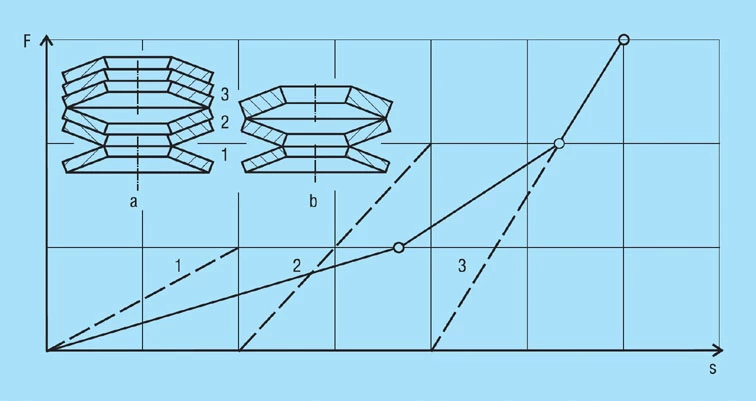
In this case it must be considered that the spring sets stacked 1 or 2-fold or the thinner single discs are subjected to high stresses if disc springs as per DIN 2093 or the factory standard have been selected. However, this overloading can be prevented with a smaller cone height or with spacer sleeves or rings to limit the deflection.
Other ways of obtaining a progressive characteristic are shown in figures 24 to 26. By inserting intermediate rings of differing thicknesses, the deflection of a spring stack consisting of disc springs of the same thickness can be limited in steps. As a result, the spring rate increases with increasing deflection (figure 24). Care must be taken to ensure that the permissible stress is not exceeded for springs without spacer rings (section 3 of the stack).
A progressive characteristic can also be obtained by combining disc springs with flat washers. With this arrangement as shown in figure 25, the discs springs of a group of 2 disc springs with a flat washer between them first deflect until all the 3 parts lie parallel. From this point on the 2 disc springs act as a parallel pair and the flat washer is unloaded again, as it moves toward its original state.
Washers and disc springs may also have different thicknesses or be arranged so that 3 or more layers result.
Figure 26 shows a stack consisting of disc springs of 3 different thicknesses. Here external rings are used as spacers to limit the deflection to protect the thinner springs from overloading.
Figure 26 – click to enlarge
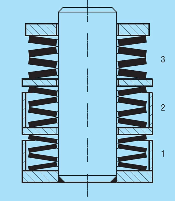
If you should have a requirement for similar spring arrangements, please contact us. We will be glad to make the appropriate calculations for you.
Introduction
- Classification by group
- Fine blanked or turned discs springs
- Heat treatment
- Scragging or presetting
- Shot peening
- Corrosion protection
CLASSIFICATION BY GROUP
The large dimensional range in which disc springs are made requires very different production methods. The methods employed range from simple stamping and stamping with extra machining to hot forged and rolled rings, which are turned or ground to obtain their final shape.
DIN 2093 specifies 3 manufacturing groups:
Group 1: Thickness t less than 1.25mm
Group 2: Thickness t from 1.25 to 6mm
Group 3: Thickness t more than 6 to 14mm
For these groups the following manufacturing methods are specified:
Group 1: Stamped/Cold formed/Corners rounded
Group 2: Stamped/Cold formed/De and Di turned/Corners radiused
Group 3: Cold or hot formed/Machined all over/Corners radiused/With contact flats and reduced thickness
All disc springs as per DIN 2093 and our factory standards are made to these requirements. Special sizes are also assigned to the appropriate group if production is possible or no other production method has been agreed upon.
The manufacturing process is shown schematically for the three groups in figure 27 below.
Disc Springs Heat Treatment
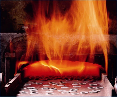
Heat treatment is of major importance for properties of a spring. Therefore, we heat treat all springs of ordinary spring steel – as long as they are not manufactured of spring-hard material – using an isothermal annealing. This enables a so-called bainite stage to ensure that the springs attain the highest strength, and at the same time a high degree of toughness and optimal fatigue resistance.
According to DIN 2093 the hardness of disc springs should be 42 – 52 HRC. With our springs, hardness is related inversely to disc thickness.
SCRAGGING OR PRESETTING
After heat treatment each spring is flattened at least once. This reduces the overall height by means of plastic deformation. Tensile stress results on the upper side, which counteracts the compressive stress caused by subsequent loadings and so reduces the stress peaks. Further plastic deformation is thereby avoided during later loading of the spring.
According to DIN 2093 each disc spring must be scragged so that following loading equivalent to twice the spring force F (s = 0.75 ho), the limit deviations for the spring force are not exceeded.
SHOT PEENING
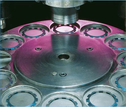
It has been shown that shot peening can be very beneficial to springs subjected to dynamic loads. It can considerably improve the working life far in excess of the values shown in figures 18, 19 and 20.
Shot peening produces compressive stress at the surface which partially counteracts internal tensile stress resulting from setting. Therefore shot-peened springs will generally set more than usual. For this reason, surface bonding by means of shot peening is not recommended for springs carrying static loads.
CORROSION PROTECTION
In practice the presence of corrosive media is no common and the forms of attack so numerous that it is not possible to deal with the entire problem in detail here. It can only be established here that ordinary spring steel must offer no corrosion protection of their own. Therefore, disc springs of these types of steel must be protected again:
Phosphating
This is a standard process generally applied to all low alloy steels unless otherwise agreed. A zinc phosphate layer is produced on the surface, which is then impregnated with corrosion-protection oil. The protection achieved in this way is sufficient in the vast majority of all cases. Primarily for inside applications, but also out of doors, if the springs are installed with weather protection, no additional protection is required.
According to DIN 50960, the designation for phosphate treatment is: Surface coating as per DIN 50942 Fe/Znph r10 f.
Browning
This process simply produces an oxidised surface, which is then coated with a corrosion-resistant oil. The corrosion resistance is not as good as phosphating, therefore this treatment is mostly used where a phosphate coating or its abrasion is a problem.
DIN50960 defines browning as follows: Surface coating as per DIN 50938 Fe/A f.
Metal Surface Treatment
Zinc is by far the most commonly used coating metal. As it lies lower than steel in the electrochemical series at room temperature, it forms a so-called cathodic protection and is attacked first by corrosion. With a chromated surface the onset of corrosion can be significantly delayed. The most effective in yellow chromating, which should always be chosen over clear chromating.
Cadmium also offers very good corrosion protection, but is only rarely used now for environmental protection reasons.
Nickel is resistant to a large number of media and is frequently used as a coating metal. It is placed higher than steel in the electrochemical series, i.e. in the cases of the formation of a local element (e.g. at a damaged point in the nickel coating) nickel acts as a cathode and the base metal is attacked. For this reason the nickel must always be a dense, non-porous coating.
Electroplating
With electroplating virtually any metal can be precipitated as a surface coating. However, when treating high-tensile steels – such as those always used for disc springs and lock washers – the danger of hydrogen embrittlement cannot be excluded with the current state of technology. Post plating bake is also no guarantee that this risk is completely eliminated. Therefore, we only use electroplating if it is specified as mandatory or there is no other alternative.
Designation of a galvanically produced 8µm thick zinc coating with transparent chromating is: Surface coating as per DIN 50961 Fe/Zn 8 cB.
Mechanical or Peen Plating
With this process the parts to be treated are moved in a barrel together with peening bodies e.g. glass beads, and a so-called promoter and the coating metal (preferably zinc) is added in powdered form. This powder is deposited on the surface and is compacted by the peening bodies. An even, mat coating results, which can then be cremated like a galvanic coating. The usual layer thickness is 8µm, however thicknesses up to 40µm are possible. It is of particular importance that no hydrogen embrittlement can occur when the process is carried out properly.
Designation of a mechanically applied 8mm thick zinc coating with yellow chromating is: Surface coating mech Zn 8 cC.
Metal Spray
This treatment is primarily for disc springs with diameter above 150mm which cannot be mechanically zinc plated. As a rule, sprayed zinc coatings are relatively thick and have a granular surface which also makes them excellently suited as a base for paints. However, the adhesion in inferior to mechanical zinc coating and it may become delaminated during dynamic loading.
Chemical Nickel Plating
With this treatment, also known as ‘electro-less nickeling’, a nickel-phosphor alloy is precipitated onto the surface with a chemical method. This results in a thick, hard layer with sharp contours and outstanding corrosive and abrasion resistance. The coating is usually applied in layers with a thickness of 15-30µm.
Dacromet Coating
This is an inorganic silver-grey metallic coating of zinc and aluminium flakes in a chromatic compound. The parts are treated in a barrel or on racks and the coating then baked on at over 280oC. Dacromet-treated springs exhibit excellent resistance in a salt spray test. With the usual processing technology there is no possibility of hydrogen embrittlement.
DISC SPRING TOLERANCES
| De or Di [mm] | Permissible deviation in mm | ||
| De | Di | Concentricity | |
| Over 3-6 | 0/-0.12 | +0.12/0 | 0.15 |
| Over 6-10 | 0/-0.15 | +0.15/0 | 0.18 |
| Over 10-18 | 0/-0.18 | +0.18/0 | 0.22 |
| Over 18-30 | 0/-0.21 | +0.21/0 | 0.26 |
| Over 30-50 | 0/-0.25 | +0.25/0 | 0.32 |
| Over 50-80 | 0/-0.30 | +0.30/0 | 0.60 |
| Over 80-120 | 0/-0.35 | +0.35/0 | 0.70 |
| Over 120-180 | 0/-0.40 | +0.40/0 | 0.80 |
| Over 180-250 | 0/-0.46 | +0.46/0 | 0.92 |
| Over 250-315 | 0/-0.52 | +0.52/0 | 1.04 |
| Over 315-400 | 0/-0.57 | +0.57/0 | 1.14 |
| Over 400-500 | 0/-0.63 | +0.63/0 | 1.26 |
| t or t’ [mm] | Tolerance at t [mm] | |
| Group 1 | 0.2-0.6 | +0.02/-0/06 |
| >0.6 -<1.25 | +0.03/-0.09 | |
| Group 2 | 1.25-3.8 | +0.04/-0.12 |
| >3.8-6.0 | +0.05/-0.15 | |
| Group 3 | >6.0-16.0 | +0.30/-0.30 |
| t [mm] | Tolerance at lo [mm] | |
| Group 1 | <1.25 | +0.10/-0.05 |
| Group 2 | 1.25-2.0 | +0.15/-0.08 |
| >2.0-3.0 | +0.20/-0.10 | |
| >3.0-6.0 | +0.30/-0.15 | |
| Group 3 | >6.0-16.0 | +0.30/-0.30 |
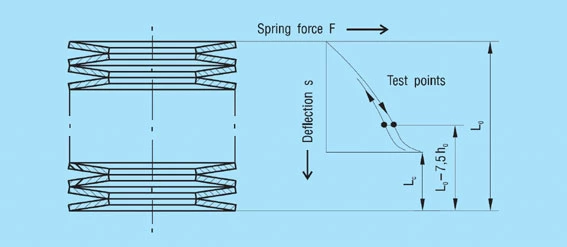
| t [mm] | Tolerance for F at the test length lp=lo-0.75 ho | |
| Group 1 | <1.25 | +25%/-7.5% |
| Group 2 | 1.25-3.0 | +15%/-7.5% |
| >3.0-6.0 | +10%/-5% | |
| Group 3 | >6.0-6.0 | +5%/-5% |

Series A | Series B | Series C | |
Group 1 | Min.90% | Min.90% | Min.85% |
Group 2 | Min.92.5% | Min.92.5% | Min.87.5% |
Group 3 | Min.95% | Min.95% | Min.90% |
Schnorr Disc Spring Tolerances For Preloading Bearings
Diameter Tolerances
For the outside diameter De, the tolerance field h12 is applied, and for the inner diameter Di, it is H12. For the concentricity the tolerances applied are: for De to 50mm: 2 . IT 11 for Di over 50mm: 2 . IT 12| De or Di [mm] | Permissible deviation in mm | ||
| De | Di | Concentricity | |
| Over 3-6 | 0/-0.12 | +0.12/0 | 0.15 |
| Over 6-10 | 0/-0.15 | +0.15/0 | 0.18 |
| Over 10-18 | 0/-0.18 | +0.18/0 | 0.22 |
| Over 18-30 | 0/-0.21 | +0.21/0 | 0.26 |
| Over 30-50 | 0/-0.25 | +0.25/0 | 0.32 |
| Over 50-80 | 0/-0.30 | +0.30/0 | 0.60 |
| Over 80-120 | 0/-0.35 | +0.35/0 | 0.70 |
| Over 120-180 | 0/-0.40 | +0.40/0 | 0.80 |
| Over 180-250 | 0/-0.46 | +0.46/0 | 0.92 |
| Over 250-315 | 0/-0.52 | +0.52/0 | 1.04 |
| Over 315-400 | 0/-0.57 | +0.57/0 | 1.14 |
| Over 400-500 | 0/-0.63 | +0.63/0 | 1.26 |
Thickness Tolerances
Tolerances allowed in DIN 2093 are as follows:| t or t’ [mm] | Tolerance at t [mm] | |
| Group 1 | 0.2-0.6 | +0.02/-0/06 |
| >0.6-<1.25 | +0.03/-0.09 | |
| Group 2 | 1.25-3.8 | +0.04/-0.12 |
| >3.8-6.0 | +0.05/-0.15 | |
| Group 3 | >6.0-16.0 | +0.30/-0.30 |
Overall Height Tolerances
To ensure the specified spring forces, DIN 2093 allows the overall height tolerance to be slightly exceeded.| t [mm] | Tolerance at lo [mm] | |
| Group 1 | <1.25 | +0.10/-0.05 |
| Group 2 | 1.25-2.0 | +0.15/-0.08 |
| >2.0-3.0 | +0.20/-0.10 | |
| >3.0-6.0 | +0.30/-0.15 | |
| Group 3 | >6.0-16.0 | +0.30/-0.30 |
Load Tolerances
Single Disc Springs
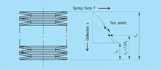
For single disc springs the following maximum deviations are allowed:| t [mm] | Tolerance for F at the test length lp=lo-0.75 ho | |
| Group 1 | <1.25 | +25%/-7.5% |
| Group 2 | 1.25-3.0 | +15%/-7.5% |
| >3.0-6.0 | +10%/-5% | |
| Group 3 | >6.0-6.0 | +5%/-5% |

Series A | Series B | Series C | |
Group 1 | Min.90% | Min.90% | Min.85% |
Group 2 | Min.92.5% | Min.92.5% | Min.87.5% |
Group 3 | Min.95% | Min.95% | Min.90% |
PERMISSIBLE SETTING
All springs experience a loss of load or relaxation in the course of time, which is primarily dependent on the occurring stress and the temperature-time curve.
For disc springs the stress distribution in the cross-section also plays a role determined by the dimensional relationships δ and ho/t. The relaxation can therefore be related to stress µOM, because it best reflects all other influences. Depending on the installation situation, the load loss may occur as creeping or relaxation. Creeping is described as a loss of length Δl which the spring suffers under a constant load F, and relaxation as a loss in load Δ F if the spring is installed at a constant length l.
Approximate values for the permissible relaxation of disc springs under static loads are provided in figure 29 and 30.
If working temperatures above 100oC occur, we recommend you contact us.
APPLICATION
Schnorr disc springs support many dynamic processes in a safe and efficient way – often under extreme force and load conditions.
With the demand to develop and manufacture perfectly fitting solutions for various applications, Schnorr offer a wide standard range of disc springs as well as customer-oriented solutions and special developments.
- Spring stacks and their features
- Alignment of spring stacks
- Guide clearance, guide elements and abutments
- Friction
Understanding the Advantages of Disc Spring Stacks
The best spring arrangement is the one which uses the least number of individual disc springs. In order to achieve this goal, the outside diameter should always be as large as possible. This automatically keeps the disc spring stack length short.
With an increasing number of disc springs, the friction and the uneven deflection of individual discs within the stack increases. We recommend Lo<3.De as the approximate spring stack length.
If it is not possible to avoid a longer stack, then it should be divided into 2 or possibly 3 partial disc spring stacks with suitable washers. These washers should be guided as exactly as possible.
In order to keep the friction within reasonable limits, no more than 2 or 3 springs should be stacked in parallel unless a large friction loss is expressly desired. Particularly in the case of dynamic loading, considerable warming must be expected with 2 or more springs in parallel. Whenever possible, the abutments of a disc spring stack should contact the outside diameter, however, this is only possible at both abutments with an even number of individual disc springs or spring sets.
Advantages of Disc Spring Stacks
- Efficient Load Distribution: Disc spring stacks provide uniform load distribution, minimising the risk of uneven deflection.
- Space Efficiency: Using larger outside diameters in disc spring stacks helps in keeping the stack length short, saving valuable space in assemblies.
- Enhanced Performance: Properly guided washers within disc spring stacks reduce friction and increase the overall efficiency of the system.
Dynamic Load - Management: Disc spring stacks are effective in managing dynamic loads, although it’s important to monitor potential warming when using multiple springs in parallel.
Best Practices for Using Disc Spring Stacks
- Optimal Stack Length: Aim for an approximate stack length of Lo<3.De to minimise friction and uneven deflection.
- Divide Long Stacks: If a longer disc spring stack is unavoidable, divide it into 2 or 3 partial stacks with guided washers for better performance.
- Friction Management: Limit the number of parallel springs to 2 or 3 to keep friction within reasonable limits unless higher friction is desired.
- Abutment Contact: Ensure that the abutments of the disc spring stack contact the outside diameter, which is achievable with an even number of springs or spring sets.
By following these guidelines, you can optimise the performance and longevity of your disc spring stacks. Whether used in static or dynamic applications, disc spring stacks are an excellent solution for efficient load management and space-saving in mechanical assemblies.
ALIGNMENT OF SPRING STACKS
Within a spring stack the disc springs do not always move evenly (figure 32).
This naturally leads to overloading at one end of the stack with consequential reduction in fatigue life. This is also the reason way, with dynamic loads, the first breaks occur at the end of the spring stack in most cases. Therefore, we recommend that the spring stack be aligned on the guide rod with a ‘vee bar’ and then maintained in position with a light preload. After alignment the spring stack should not be completely relaxed. This procedure has been found most satisfactory in practice for minimizing friction in spring stacks. If it is not possible to align the stack for design reasons, the stack should be compressed flat once or twice. This also has the effect of centralising the springs and reducing friction.
Figure 32 – click to enlarge
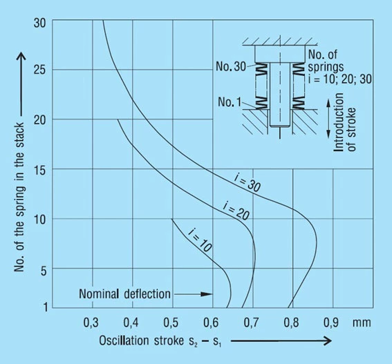
The friction is usually somewhat less in a vertically arranged stack than in the horizontal installation position. It is therefore better to have long stacks arranged vertically rather than horizontally.
With a dynamically loaded stack there is a running in period during which the friction is reduced, especially with multiple layering. The reason for this is a certain smoothing effect at both the contact edges and the touching spring flanks.
GUIDE CLEARANCE
| Di or De [mm] | Clearance [mm] |
| To 16 | 0.2 |
| Over 16 to 20 | 0.3 |
| Over 20 to 26 | 0.4 |
| Over 26 to 31.5 | 0.5 |
| Over 31.5 to 50 | 0.6 |
| Over 50 to 80 | 0.8 |
| Over 80 to 140 | 1.0 |
| Over 140 to 250 | 1.6 |
Figure 33 – click to enlarge
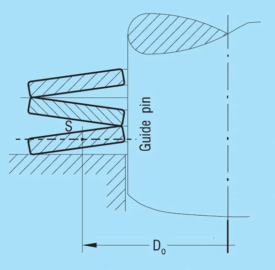
Guide Elements & Abutments
The guide elements and abutments should be hardened if possible to a minimum of 55HRC and a minimum case depth of 0.8mm.
The surface of the guide rod should be smooth and, if possible, ground. For dynamic applications we recommend lubrication with a high pressure grease containing MoS2. For static applications guides may be unhardened.
DISC SPRINGS FRICTION
Causes of Friction
The total friction with disc spring stacks arises because of 4 different components (figure 34 below):
The Magnitude and Factors Influencing Friction
The amount of friction depends on very many factors: Geometric factors:- Shape of the cross section
- Radii on the corners
- Amount of guide clearance
- Surface roughness of the springs and guide elements
- Material of the springs and guide elements
- Hardness of the springs and guide elements
- Surface protection of the springs
- Type of lubricant
- Number of parallel stacked springs
- Length of the spring stack
- Length of spring stroke
- Speed of loading (frequency)
| Influence of friction on spring load | |
| 1 single spring | +2… 3% |
| 2 in parallel | +4… 6% |
| 3 in parallel | +6… 9% |
| 4 in parallel | +8… 12% |
| 5 in parallel | +10… 15% |
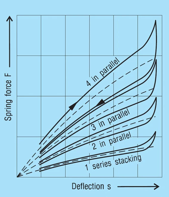
Calculation of Friction as per DIN 2092
DIN 2092, Issue 1/92 gives a method of calculating the friction FR on spring load. This omits the internal friction and the friction on the guide rod. This must be obtained through an additional calculation. The values below for surface and edge friction to DIN 2092 give a relatively wide range.
Therefore, it is our opinion that, although this process is theoretically correct, in the end it does not provide any better results than the consideration of the friction with a simple, percentile addition. For completeness, we have shown this calculation method below.
The following formula applies:
Formula 26

Where:
F = Calculated spring load to formula 7
n = Number of springs in parallel
WM = Coefficient of surface friction
WR = Coefficient of edge friction
– = On loading
+ = On unloading
With n = 1 formula 26 describes relationships for a single spring between 2 flat plates. For the friction coefficients WM and WR, DIN 2092 gives the following values:
Series Per DIN 2093 | WM | WR |
| Series A | 0.005…0.030 | 0.03…0.05 |
| Series B | 0.003…0.020 | 0.02…0.04 |
| Series C | 0.002…0.015 | 0.01…0.03 |
When calculated with these values, formula 26 provides the following numbers, which are considerably easier to understand:
Alteration of the calculated spring load through the friction is in %.
+ = Increase in load when loading / – = Reduction in load when unloading
| n = 1 | n = 2 | n = 3 | |
| Series A | +3.09…+5.26 | +3.63…+8.70 | +4.17…+12.36 |
| -2.91…-4.76 | -3.38…-7.41 | -3.85…-9.91 | |
| Series B | -2.04…+4.17 | +2.35…+6.38 | +2.67…+8.70 |
| -1.96…-3.85 | -2.25…-5.66 | -2.53…-7.41 | |
| Series C | +1.01…+3.09 | +1.21…+4.71 | +1.42…+6.38 |
| -0.99…-2.91 | -1.19…-4.31 | -1.38…-5.66 |
These results are presented in figure 36 below.
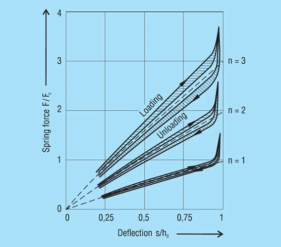
Lubrication
The large variation in figure 36 shows the influence of lubrication on the friction. The choice of the correct lubricant is therefore often of decisive influence. As well as reducing friction. It can prevent galling of one spring on another when stacked in parallel. Similarly, it can help prevent corrosion. The lubricants which may be used are:
- Oil is frequently used for springs in machine construction, especially with central lubrication or an assured continuous oil supply.
- Grease is more suitable if re-lubrication is difficult or cannot be done on a regular basis.
- Slip paints are based on MoS2 and are an elegant solution to providing permanent lubrication. It also provides a high degree of corrosion resistance.
The Effects of Friction
Friction mainly effects the deflection of the spring, i.e. it modifies the spring loads. It must be added when loading the spring and subtracted when the spring is unloaded. Between the actual loading and unloading curve there is a hysteresis loop. The effect of the number of parallel springs on the hysteresis is shown in figure 35. This frictional work is turned into heat and with high frequency dynamic loading this can be considerable. In such cases, single stacked discs springs should be preferred and good lubrication is essential.
With spring energy storage the hysteresis is a total loss and cannot be recovered. However, with springs for damping, this hysteresis effect is useful and the frictional work is a measure of the damping.
MATERIALS - GENERAL REQUIREMENTS
The essential of a spring is that is has the quality to react to loading by elastic deformation. Therefore, materials with high elasticity are necessary. As in each case a small design is desired, spring materials should have the hightensile strength and a high elastic limit.
In addition to high strain in the elastic region, there must also be sufficient plasticity. This allows the manufacture of cold formed springs which will not break through the greatest unforeseen overloading.
Moreover, a high fatigue limit is required which is however not a characteristic value of the material as, for example, the tensile strength. For a high fatigue strength, a high degree of purity, a homogenous structure and a smooth carbon-free surface are pre-supposed.
These requirements are fulfilled very well by steel, therefore most springs are made of steel. Apart from this there will be the requirement in some cases for corrosion resistance, heat resistance or anti-magnetic properties where special materials will be required.
An important property of spring material is Young’s Modulus (E). From this material constant is derived a linear relationship between load and deflection. The ‘E’ of steel is practically not affected by heat treatment, but it is temperature dependent and this must be taken into consideration at higher working temperatures.
Materials for disc springs are principally supplied in the following forms:
- Cold rolled trip as per DIN EN 10140
- Hot rolled strip as per DIN EN 10048
- Plate as per DIN EN 10029
- Forgings as per DIN 7521 and 7526
The materials table lists the properties of all the materials from which disc springs are manufactured.
STANDARD MATERIALS
C 60S
Both types are quality steels as per DIN EN 10132-4. We use them for our original Schnorr Serrated Safety Washers and Load Washers as per DIN 6796 where the loading is only static.
C 67S and C 75S
These high grade steels as per DIN EN 10132-4 are used for cold formed springs to group 1. For lightly loaded springs, for example our ‘K’ springs for preloading ball bearings, these materials can be processed in the spring-hard condition.
51 CrV 4 (1.8159)
This is a chrome vanadium refined alloy steel of the highest quality. It is available in cold rolled form as per DIN EN 10132-4, hot rolled and forgings as per DIN 17221 for the manufacture of disc springs. It has very good through-hardening capability and is therefore suitable for making springs up to 50mm thick. The relaxation is less than for non-alloyed steel, which allows use up to 250oC (with a suitable reduction in load).
MATERIALS FOR SPECIAL REQUIREMENTS
Special requirements such as corrosive or high temperature environments often require the use of materials designed for these applications. These materials, in general, have lower tensile strength than standard materials and should only be, if absolutely necessary. These springs have a lower overall height than comparable sizes made of standard materials resulting in lower spring force. This must be taken into consideration using these materials.
Corrosion Resistant Steels
X 10 CrNi 18-8 (1.4310): This chrome nickel alloyed steel as per DIN EN 10151 is the material most used for corrosion resistant springs. Because of its austenitic structure with ferritic inclusions, it cannot be hardened in the usual way, but by cold forming it can obtain the strength required for disc springs. Considerable cold forming in necessary and the strength reduces with increasing thickness. Therefore, the material is normally not available thicker than 2.5mm. In fact, springs can only be supplied to this thickness. Whereas the material in the soft condition is hardly magnetic, the cold working process will make it more or less magnetic again, making it unsuitable for completely non-magnetic springs.
X 7 CrNiAI 17 7 (1.4568): This steel as per DIN EN 10151 precipitation hardened produces an austenitic/ferritic structure. It will also be processed in the work hardened condition and may be hardened by subsequent heat treatment. A disadvantage compared to steel 1.4310 is the lower corrosion resistance and sensitivity to stress corrosion. We therefore only recommend its use for springs over 2.5mm thickness if no other material is available.
X 5 CrNiMo 17 12 1 (1.4401): The strength of this material is somewhat less than either of the two forgoing. Not withstanding that it offers higher corrosion resistance and lowest magnetism. Although also contained in DIN 17224, it is often difficult to obtain and therefore only seldom used.
Steels for Higher Temperatures
When considering springs for use at higher working temperatures it must be remembered that both tensile strength and Young’s modulus ‘E’ are reduced compared with the values at room temperature.
X 22 CrMoV 12 1 (1.4923): This heat treatable chrome-molybdenum steel has been used very successfully for heat resistant disc springs. Springs of 1.5 to 6mm thickness are made from strip or plate. For thicker springs, forged rings can be used.
Figure 38 shows the mechanical properties and Young’s modulus ‘E’ with respect to temperature. It should be noted that with a chrome content of 12% this steel is not corrosion resistant.
Figure 38 – click to enlarge
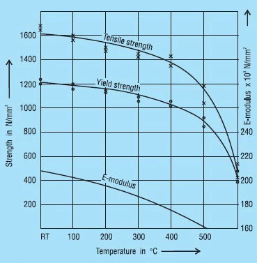
X 39 CrMo 17 1 (1.4122): Here we have a chrome-molybdenum alloyed heat treatable martensitic steel which is also suitable for corrosion resistant springs. Because of the molybdenum is may be used up to 400oC. However, at these temperatures both the tensile strength and ‘E’ are reduced.
In order to achieve the required properties, this steel must be hardened to higher values which raises the question of stress corrosion. Unfortunately, in the light of current technical knowledge we cannot completely discount the possibility of delayed brittle fracture.
Copper Alloys
Copper alloys are absolutely non-magnetic and have very good electric conductivity. Moreover, they are corrosion-resistant against many media. These characteristics make them suitable for many disc spring applications.
CuSn 8 (2.1030): Tin bronze as per DIN EN 1654 is an alloy of copper and tin, which obtains is spring properties from cold working. The tensile strength is certainly lower than spring steel and the ‘E’ modulus is only 55% of the value for steel. This must be considered in the spring calculation and allows their use in applications where very low spring loads are required.
CuBe 2 (2.1247): Beryllium copper is an outstanding spring material. This heat treatable alloy has strength values comparable with steel. However, Young’s modulus ‘E’ is only 60% of that for steel. It has very good corrosion resistance and may be used at very low temperatures nearing absolute zero.
Nickel and Cobalt Alloys
From the large number of nickel-chrome and nickel-chrome-cobalt based alloys some have achieved importance for disc springs. By alloying the aluminium, titanium and/or niobium/tantalum they are precipitation hardenable. These materials are very tough, that is to say they have high strength and a low elastic ration. Therefore, the probability of more set in the spring must be considered. Against this are the outstanding fatigue properties. With correct spring proportions this is good over the total spring travel. Because of the material composition they have outstanding corrosion resistant to many media. All these alloys are very expensive and often hard to work, and as a rule have long deliveries. They are therefore only used where no other material is suitable due to technical considerations.
NiCr 20 Co 18 Ti (Nimonic 90) (2.4632, 2.4969): These nickel-chrome-cobalt alloy gives the least problems in processing and is therefore the most often used. It has very good heat resistance and can be used up to 700oC with suitable dimensioning.
NiCr 15 Fe 7 TiAi (Inconel X 750) (2.4669) and NiCr 19 NbMo (Inconel 718) (2.4668): These nickel-chrome alloys are practically cobalt-free, and are therefore used in reactor applications. The hardening process is difficult and expensive. The application is limited and only used in special cases. NIMONIC and INCONEL are trade names of Inco Alloys International.
DURATHERM 600: This is a heat treatable alloy of the cobalt-nickel series with outstanding mechanical properties. At a temperature of 0oC the material in non-magnetic. It can be used at very high temperatures (600oC and over). The very high price of this alloy limits its use to very special applications. DURATHERM is a trade name of Vacuumschmelze GmbH in Hanau.
DISC SPRINGS FOR PRELOADING BEARINGS
With every ball bearing there is radial play so it may function correctly.
This radial play or clearance can cause considerable noise at high speeds. In many cases it is possible to achieve a quiet running bearing assembly by the use of a suitable disc spring to apply an axial load to the bearing.
Similarly, the springs can be used to accommodate the build up of tolerances or thermal movements within the assembly.
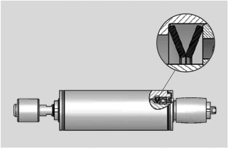
In addition to the normal range ‘slotted’ springs are available up to a diameter of 95mm. This special design generates very small loads and will accommodate large deflections.
The load and dimension tolerances of DIN 2093 do not apply to this type of disc spring.
For the dimensions of ‘K’ Disc springs click here.
SLOTTED DISC SPRINGS
The inclusion of slots on either the inner or outer diameter creates a lever which works on the unslotted portion of the spring. This has the effect of reducing the spring load and increasing the deflection (figure 39).
Figure 39 – click to enlarge
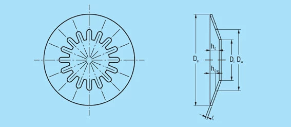
Slotted disc springs have a softer characteristic with a large deflection and, in proportion to the outside diameter, smaller spring loads. It is crucial with this type of spring that the permissible stresses in the annular portion are not exceeded. If necessary, the outside diameter must be increased to compensate.
Taking these limitations and a few design features into account, slotted disc springs offer many possible applications. The classic example is the automotive clutch spring. Notable are the slotted ball bearing preload springs which give extremely low loads.
The first approximation for the calculation of slotted disc springs can be achieved by considering the lever arm and the formula on page ‘Equations for calculations‘. The loads generated depend largely on the shape of the slots or the corresponding fingers. The deflection of the fingers is only a small percentage of the total deflection and can be ignored.
Benefits of Slotted Disc Springs:
- Enhanced Flexibility: The slots in slotted disc springs provide increased deflection, making them ideal for applications requiring greater movement.
- Load Reduction: These springs offer reduced spring loads while maintaining effectiveness, crucial for sensitive applications.
- Versatile Applications: Widely used in automotive clutches, slotted disc springs are also excellent for ball bearing preload applications, providing low load and high precision.
- Stress Management: Proper design ensures that stresses in the annular portion are managed effectively, preventing overloading and extending spring life.
- Customisable Designs: Depending on the application, the shape and placement of slots can be tailored to achieve specific load and deflection characteristics.
If you need to consider the use of slotted disc springs, please contact us to discuss your application needs. IEC provides expert guidance to ensure your springs meet the precise requirements of your application.
DISC SPRINGS WITH TRAPEZOIDAL CROSS-SECTION
By the use of a trapezoidal cross-section it is possible to equalise the stresses on the spring upper and lower surfaces. The advantageous tensile stresses on the lower surface contribute to a better fatigue life. The equal compressive stresses at points ll and lll to give the optimum fatigue life can also be achieved with a rectangular cross-section spring if the ratios δ and ho/t are correctly chosen. In this regard therefore, the trapezoidal cross-section offers no advantages. Compared with a standard spring having a similar angle on the top surface, a trapezoidal spring will give less deflection. This can be increased by including intermediate rings, but these will also increase the overall stack length and require more space.
Figure 40 – click to enlarge
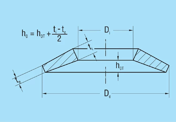
The main advantage of the trapezoidal cross-section disc spring is the ability to limit the stroke without additional parts. It is therefore possible to design a spring which is relatively fatigue free over the complete deflection range with relatively little increase in load towards the end of the stroke.
With the same installation space and under consideration of the permissible stresses, no more favourable spring data (more force or more deflection) can be achieved with disc springs with a trapezoidal cross-section than with springs with a square cross-section.
These few advantages and the higher manufacturing costs are the reasons why the trapezoidal disc spring is of no practical importance today.


